ASSEMBLY
To hire an authorized service technician to assemble the treadmill, call
Assembly requires two persons. Set the treadmill in a cleared area and remove all packing materials. Do not dispose of the packing materials until assembly is completed. Note: The underside of the treadmill walking belt is coated with
Assembly requires the included hex key and your own phillips screwdriver | . |
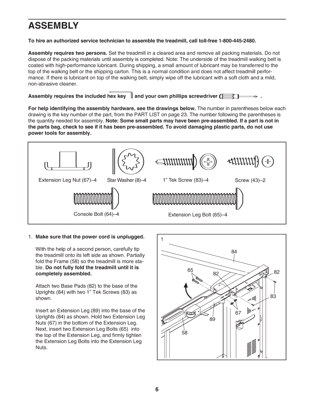
For help identifying the assembly hardware, see the drawings below. The number in parentheses below each drawing is the key number of the part, from the PART LIST on page 23. The number following the parentheses is the quantity needed for assembly. Note: Some small parts may have been
Extension Leg Nut | Star Washer | 1” Tek Screw | Screw |
Console Bolt | Extension Leg Bolt |
| |
1. Make sure that the power cord is unplugged. | 1 |
| |
|
|
| |
With the help of a second person, carefully tip |
| 84 | |
the treadmill onto its left side as shown. Partially |
| ||
|
| ||
fold the Frame (58) so the treadmill is more sta- |
|
| |
ble. Do not fully fold the treadmill until it is | 65 | 82 | |
completely assembled. |
| ||
| 82 | ||
Attach two Base Pads (82) to the base of the |
|
| |
Uprights (84) with two 1” Tek Screws (83) as |
| 83 | |
shown. |
|
| |
|
|
| |
Insert an Extension Leg (89) into the base of the |
| 67 | |
Uprights (84) as shown. Hold two Extension Leg |
| ||
89 |
| ||
Nuts (67) in the bottom of the Extension Leg. |
| ||
|
| ||
Next, insert two Extension Leg Bolts (65) | into | 58 |
|
the top of the Extension Leg, and firmly tighten |
| ||
|
| ||
the Extension Leg Bolts into the Extension Leg |
|
| |
Nuts. |
|
|
|
|
| 6 |
|