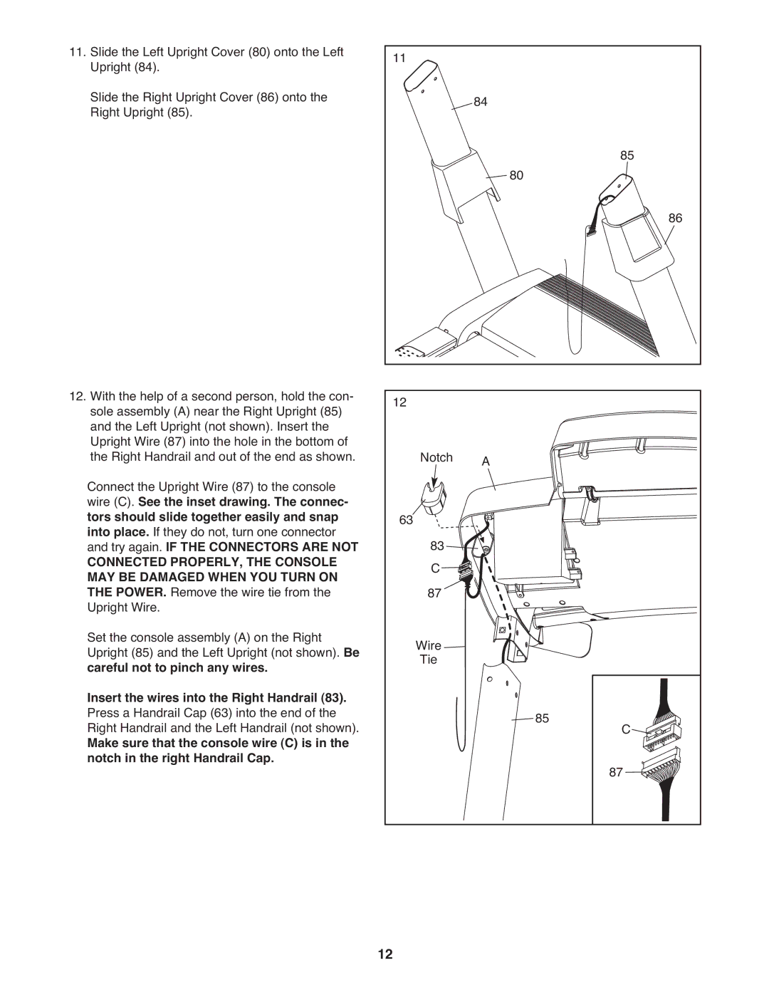
11. Slide the Left Upright Cover (80) onto the Left | 11 |
|
|
|
Upright (84). | 84 |
|
| |
Slide the Right Upright Cover (86) onto the |
|
|
| |
Right Upright (85). |
|
|
|
|
|
| 80 |
| 85 |
|
|
|
| |
|
|
|
| 86 |
12. With the help of a second person, hold the con- | 12 |
|
|
|
sole assembly (A) near the Right Upright (85) |
|
|
| |
and the Left Upright (not shown). Insert the |
|
|
|
|
Upright Wire (87) into the hole in the bottom of | Notch | A |
|
|
the Right Handrail and out of the end as shown. |
|
| ||
Connect the Upright Wire (87) to the console |
|
|
|
|
wire (C). See the inset drawing. The connec- |
|
|
|
|
tors should slide together easily and snap | 63 |
|
|
|
into place. If they do not, turn one connector |
|
|
| |
and try again. IF THE CONNECTORS ARE NOT | 83 |
|
|
|
CONNECTED PROPERLY, THE CONSOLE | C |
|
|
|
MAY BE DAMAGED WHEN YOU TURN ON |
|
|
| |
THE POWER. Remove the wire tie from the | 87 |
|
|
|
Upright Wire. |
|
|
|
|
Set the console assembly (A) on the Right | Wire |
|
|
|
Upright (85) and the Left Upright (not shown). Be |
|
|
| |
careful not to pinch any wires. | Tie |
|
|
|
Insert the wires into the Right Handrail (83). |
|
|
|
|
Press a Handrail Cap (63) into the end of the |
|
| 85 |
|
Right Handrail and the Left Handrail (not shown). |
|
| C | |
Make sure that the console wire (C) is in the |
|
|
| |
notch in the right Handrail Cap. |
|
|
| 87 |
|
|
|
| |
| 12 |
|
|
|