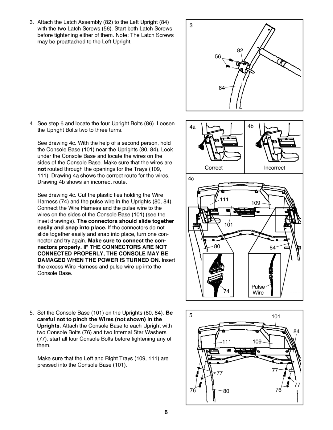
3.Attach the Latch Assembly (82) to the Left Upright (84) with the two Latch Screws (56). Start both Latch Screws before tightening either of them. Note: The Latch Screws may be preattached to the Left Upright.
3
82
56
84![]()
4. See step 6 and locate the four Upright Bolts (86). Loosen | 4a |
| 4b |
the Upright Bolts two to three turns. |
| ||
|
|
| |
See drawing 4c. With the help of a second person, hold |
|
|
|
the Console Base (101) near the Uprights (80, 84). Look |
|
|
|
under the Console Base and locate the wires on the |
|
|
|
sides of the Console Base. Make sure that the wires are |
| Correct | Incorrect |
not routed through the openings for the Trays (109, |
| ||
111). Drawing 4a shows the correct route for the wires. | 4c |
|
|
Drawing 4b shows an incorrect route. |
|
| |
|
|
| |
See drawing 4c. Cut the plastic ties holding the Wire |
| 111 |
|
Harness (74) and the pulse wire in the Uprights (80, 84). |
| 109 | |
Connect the Wire Harness and the pulse wire to the |
|
|
|
wires on the sides of the Console Base (101) (see the |
|
|
|
inset drawings). The connectors should slide together |
| 101 |
|
easily and snap into place. If the connectors do not |
|
| |
|
|
| |
slide together easily and snap into place, turn one con- |
|
|
|
nector and try again. Make sure to connect the con- |
| 80 |
|
nectors properly. IF THE CONNECTORS ARE NOT |
| 84 | |
CONNECTED PROPERLY, THE CONSOLE MAY BE |
|
|
|
DAMAGED WHEN THE POWER IS TURNED ON. Insert |
|
|
|
the excess Wire Harness and pulse wire up into the |
|
|
|
Console Base. |
|
|
|
|
| 74 | Pulse |
|
| Wire | |
5. Set the Console Base (101) on the Uprights (80, 84). Be | 5 |
| 101 |
careful not to pinch the Wires (not shown) in the |
| ||
|
|
| |
Uprights. Attach the Console Base to each Upright with |
|
| 84 |
two Console Bolts (76) and two Internal Star Washers |
|
| |
(77); start all four Console Bolts before tightening any of |
| 111 | 109 |
them. |
| ||
|
|
| |
Make sure that the Left and Right Trays (109, 111) are |
|
|
|
pressed into the Console Base (101). |
|
| 77 |
|
| 77 | |
|
|
| |
| 76 | 80 | 77 |
| 76 |
6