Manuals
/
PVI Industries
/
Household Appliance
/
Water Heater
PVI Industries
PV500-45U
manual
Burner Assembly Optional components may or may not be shown
Models:
PV500-45U
1
36
42
42
Download
42 pages
10.67 Kb
33
34
35
36
37
38
39
40
Troubleshooting
Install
Error codes
Loss of Flame Signal
Maintenance
Below scalding temperatures
Replacement Parts
Safety
Service Clearances
Page 36
Image 36
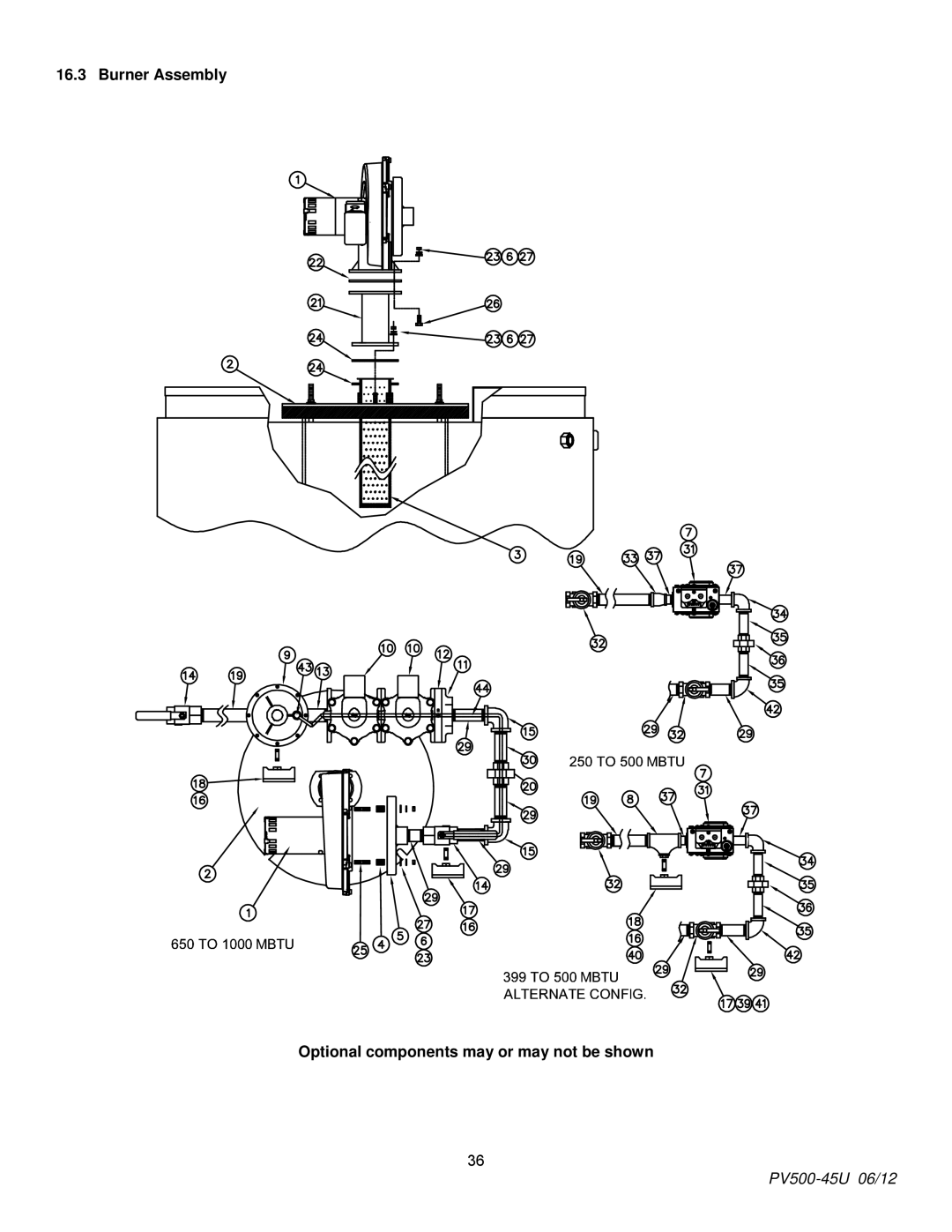
16.3 Burner Assembly
Optional components may or may not be shown
36
PV500-45U
06/12
Page 35
Page 37
Page 36
Image 36
Page 35
Page 37
Contents
Installation & Maintenance Manual
Table of Contents
Operating and Safety Controls
Troubleshooting Guide Replacement Parts
Temptrac Electronic Controller Panel
Remote Connections Terminal Strip
Safety Considerations
Product Safety Information
Below scalding temperatures
Standard Features and Equipment
Series
Series
Series
Water Heater Installation
Checking Equipment Before You Install
Codes
Electrical Requirements
Service Clearances
Clearances To Combustible Surfaces
General Piping Guidelines
Inlet and Outlet Connections
PV500-45U 06/12
PV500-45U 06/12
Optional Condensate Neutralization System
GAS Supply and Piping
Inlet Pressure NAT. GAS
Convert Fittings to Equivalent Straight Pipe
Single Unit Installation Suggested Pipe Size
Multiple Unit Installations GAS Piping Size Chart
Nominal Iron Length of Pipe in Straight Feet
Inches
Combustion and Ventilation AIR
Duct Fitting Equivalent Length Duct Pipe
Vertical or Horizontal Remote Air Duct Termination
Venting
Venting the Tricon
Maximum Category IV Vent Length Equivalent Length
Vent Fitting Equivalent Length Vent Pipe
Combining Category IV Vents
Operating and Safety Controls
Temperature and Pressure Relief Valve s
High Water Temperature Limit Control
Cathodic Protection
Electronic Low Water Cut-Off Optional
Temptrac Electronic Controller Panel
SET
Down
Clock
To View The Setpoint
To Change The Setpoint
To Change Other Parameters
LED Display Alarm Messages
Alarm Cause Results of Alarm Condition Message
Recommended Action
Remote Connections Terminal Strip
Sequence of Operation
Incoming 120VAC
Loss of Flame Signal
LED Indication Fault Mode
Initial Startup
Turn-on main gas shutoff valve
PV500-45U 06/12
Gas Train Illustration for Models 40 through
Gas Train Illustration for Models 65 through
Troubleshooting Guide
Problem Probable Cause Corrective Action
Replacement Parts
Replacement Parts
Control Panel
Contact factory for more information
Burner Assembly Optional components may or may not be shown
Contact factory for more information
Item No Qty PVI Part No Description
Periodic Maintenance
PV500-45U 06/12
Recommended Maintenance Schedule
PV500-45U 06/12
PV500-45U 06/12
Top
Page
Image
Contents