Manuals
/
PVI Industries
/
Household Appliance
/
Water Heater
PVI Industries
manual Gas Train Illustration for Models 40 through, PV500-45U06/12
Models:
PV500-45U
1
31
42
42
Download
42 pages
10.67 Kb
28
29
30
31
32
33
34
35
<
>
Troubleshooting
Specs
Install
Replacement Parts
Maintenance
Burner Assembly
14.5Startup Procedure
Fault Mode
11.8LED Display Alarm Messages
Burner Combustion Adjustment
Page 31
Image 31
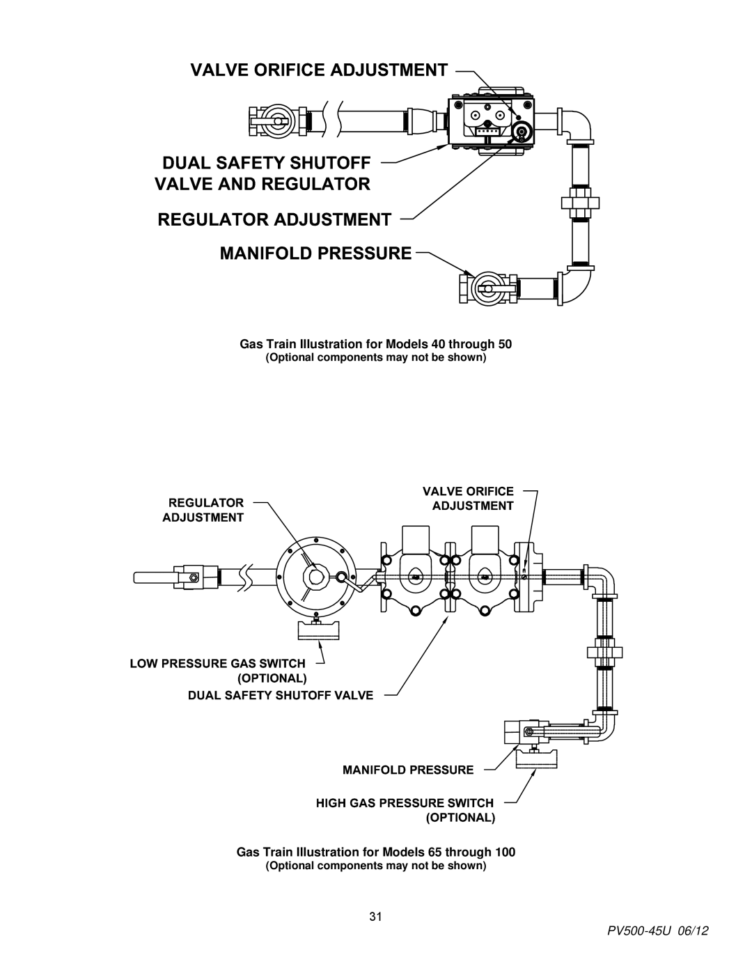
Gas Train Illustration for Models 40 through 50
(Optional components may not be shown)
Gas Train Illustration for Models 65 through 100
(Optional components may not be shown)
31
PV500-45U
06/12
Page 30
Page 32
Page 31
Image 31
Page 30
Page 32
Contents
TRICON WATER HEATER
INSTALLATION & MAINTENANCE MANUAL
PV500-45U06/12
3.Product Descriptions
TABLE OF CONTENTS 1.Safety Considerations
2.Standard Features and Equipment
4.Water Heater Installation
18.Recommended Maintenance Schedule
10.Operating and Safety Controls
15.Troubleshooting Guide 16.Replacement Parts
17.Periodic Maintenance
PRODUCT SAFETY INFORMATION
1 SAFETY CONSIDERATIONS
PV500-45U06/12
ELDER CARE FACILITIES AND REST HOMES
HOMES FOR THE MENTALLY HANDICAPPED
HOMES FOR THE PHYSICALLY HANDICAPPED
HOSPITALS AND NURSING HOMES
2.4Codes and Standards
2 STANDARD FEATURES AND EQUIPMENT 2.1Performance
2.2Pressure Vessel
2.3Heat Exchanger
PV500-45U06/12
125 SERIES
PV500-45U06/12
250 SERIES
PV500-45U06/12
300 SERIES
4.3Electrical Requirements
4 WATER HEATER INSTALLATION
4.1Checking Equipment Before You Install
4.2Codes
5.1Inlet and Outlet Connections
4.5Service Clearances
4.6Clearances To Combustible Surfaces
5 GENERAL PIPING GUIDELINES
PV500-45U06/12
SINGLE WATER PIPING
6CONDENSATE DRAIN, TRAP & DISPOSAL
TWO WATER HEATERS WITH REVERSE RETURN PIPING
PV500-45U06/12
Optional Condensate Neutralization System
6.1Condensate Neutralization System optional
PV500-45U06/12
7.3Inlet Pressure
7GAS SUPPLY AND PIPING
7.1Gas Train and Controls Certification
7.2Gas Control Trains
MBTU/HR Based on 0.5 W.C. Pressure Drop
SINGLE UNIT INSTALLATION SUGGESTED PIPE SIZE
MULTIPLE UNIT INSTALLATIONS GAS PIPING SIZE CHART
Maximum Capacity for Natural Gas
∙All Air From Outdoors
7.7Gas Connection
8COMBUSTION AND VENTILATION AIR
8.1Equipment Located In Confined Spaces
6” Duct
Remote Air Duct Specifications
Maximum Air Inlet Duct Equivalent Length
Duct Size
Maximum Category IV Vent Equivalent Length
Vertical Remote Air
Horizontal Remote Air
9 VENTING 9.1Venting the TRICON
Vent Pipe
Venting Specifications
Volume cfm
Vent Fitting Equivalent Length
Combining Vents with a Draft Inducer
10OPERATING AND SAFETY CONTROLS
Conventional Venting
Through the Wall Venting
PV500-45U06/12
10.3High Water Temperature Limit Control
10.4Cathodic Protection
10.5Electronic Low Water Cut-OffOptional
11.3Upper Led Readout
11 TEMPTRAC ELECTRONIC CONTROLLER PANEL
11.1Principle Of Operation
11.2Lower Led Readout
PV500-45U06/12
11.5To View The Setpoint
11.6To Change The Setpoint
11.7To Change Other Parameters
CAUSE
11.8LED Display Alarm Messages
ALARM
RESULTS OF ALARM CONDITION
PV500-45U06/12
13SEQUENCE OF OPERATION 1.Incoming 120VAC
PV500-45U06/12
7.Loss of Flame Signal
FAULT MODE
LED INDICATION
14.2Tools and Instrumentation Required Resources
14.5Startup Procedure
14 INITIAL STARTUP
14.1Initial Startup Requirements
16.Turn-onmain gas shutoff valve
13.Turn-offmain gas shutoff valve
PV500-45U06/12
PV500-45U06/12
Burner Combustion Adjustment
Optional components may not be shown
Gas Train Illustration for Models 40 through
Gas Train Illustration for Models 65 through
PV500-45U06/12
Corrective Action
15 TROUBLESHOOTING GUIDE
Problem
Probable Cause
16 REPLACEMENT PARTS
REPLACEMENT PARTS
PV500-45U06/12
PV500-45U06/12
16.1 Control Panel
PV500-45U06/12
Contact factory for more information
16.2Control Panel Components
Optional components may not be included
Optional components may or may not be shown
16.3 Burner Assembly
PV500-45U06/12
PV500-45U06/12
16.4Burner Assembly Components
Optional components may not be included
Contact factory for more information
PV500-45U06/12
17PERIODIC MAINTENANCE
PV500-45U06/12
i.Cycle unit and test to verify all safety and operating controls are properly functioning and the burner top plate flange is free of leaks
4.Daily Maintenance
18RECOMMENDED MAINTENANCE SCHEDULE
1.Annual Maintenance
3.Monthly Maintenance
PV500-45U06/12
PV500-45U06/12