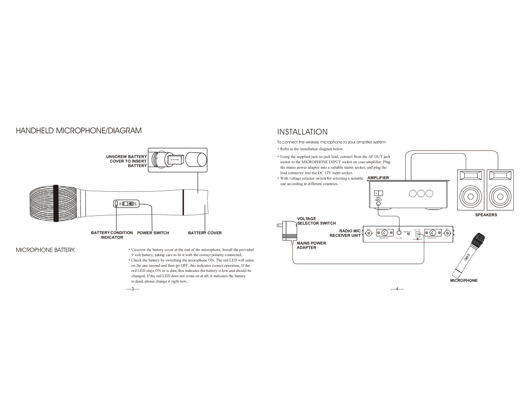
HANDHELD MICROPHONE/DIAGRAM
UNSCREW BATTERY
COVER TO INSERT
BATTERY
| BATTERY CONDITION POWER SWITCH | BATTERY COVER |
| INDICATOR |
|
MICROPHONE BATTERY. | Unscrew the battery cover at the end of the microphone, Install the provided | |
| 9 volt battery, taking care to fit it with the correct polarity connected, | |
| Check the battery by switching the microphone ON, The red LED will come | |
on for one second and then go OFF, this indicates correct operation, If the red LED stays ON or is dim, this indicates the battery is low and should be changed, If the red LED does not come on at all, it indicates the battery is dead, please change it right now,
INSTALLATION
To connect the wireless microphone to your amplifier system:
![]() Refer to the installation diagram below.
Refer to the installation diagram below.
![]() Using the supplied
Using the supplied
With voltage selector switch for selecting a suitable AMPLIFIER one according to different countries.
SPEAKERS
VOLTAGE SELECTOR SWITCH
RADIO MIC | ANT | MIX | SQUELCH | ANT |
|
|
| DC 12V |
|
RECEIVER UNIT |
|
|
|
|
| BALANCED | AF. OUT |
| BALANCED |
MAINS POWER
ADAPTER
MICROPHONE
