
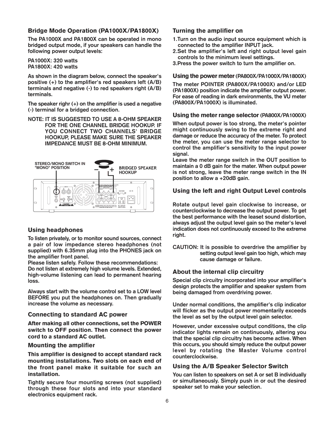
PA600X, PA1800X, PA1000X, PA800X specifications
Pyramid Car Audio has long been a respected name in the automotive sound industry, and its PA series amplifiers—namely the PA1800X, PA600X, PA800X, and PA1000X—continue to uphold this tradition with exceptional performance, innovative technology, and user-friendly features.The PA1800X is the flagship model that showcases Pyramid's commitment to delivering high power output and pristine sound quality. With a maximum power output of up to 1800 watts, this amplifier is designed to drive subwoofers and deliver explosive bass while maintaining audio clarity. The integrated variable low-pass filter allows users to tailor their sound experience, ensuring that the low frequencies come through with fullness and depth.
Similarly, the PA1000X and PA800X models are designed with versatility in mind, making them suitable for both high and low-end audio systems. The PA1000X offers a maximum power output of 1000 watts, making it an excellent choice for those who want robust sound without compromising on quality. The PA800X, while slightly lower in wattage, provides a solid power range perfect for mid-level audio setups. Both these models feature a variable bass boost, allowing users to increase low-frequency output for a more immersive experience.
On the other end of the spectrum, the PA600X offers a more compact and economical solution, providing a maximum power output of 600 watts. This amplifier is ideal for smaller cars or budget-conscious consumers who still wish to enhance their audio experience without overwhelming their vehicle’s electrical system.
All models in the PA series are equipped with advanced protection technologies, including over-voltage, over-current, and thermal protection, ensuring reliability and longevity. The rugged construction and efficient heat dissipation systems further add to their durability, making them suitable for all types of vehicles and driving conditions.
With their million-dollar sonic performance, Pyramid’s PA series amplifiers also feature RCA input connectors for easy installation, chrome-plated connections for corrosion resistance, and a stylish design that complements any vehicle interior. These amplifiers are engineered to provide audiophiles or casual listeners alike with the power and clarity they seek, whether they are enjoying a relaxing drive or jamming out on the open road.
In conclusion, the Pyramid Car Audio amplifiers PA1800X, PA600X, PA800X, and PA1000X are prime choices for anyone looking to enhance their car audio experience, presenting a compelling blend of power, performance, and advanced technology. With versatile features and rugged construction, these amplifiers cater to a wide variety of audio enthusiasts.