LCD WITH BUILT-IN DVR USER MANUAL
3.3 .2 CHANNEL SETU P
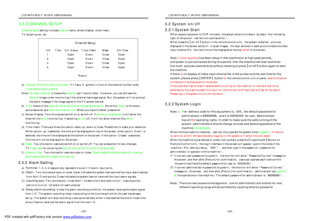
Channel setup setting includes channel name, screen display, clock insert,
TV screen cover, etc
Channel Setup
CH | Title CH Name | Time InSert | Mask | CH View |
1 | Open | Down | Close | Open |
2 | Open | Down | Close | Open |
3 | Open | Down | Close | Open |
4 | Open | Down | Close | Open |
Return
a). Channel: Enter the channel number. If it has a X symbol in front of the channel number code, it indicates invalid channel.
Note: For each channel, it means the channel can't record video. However, you can still see the channel image under monitoring if the channel has image signal. But, the system will not prompt the alarm message if the image signal of this TV screen has lost.
b). Title: Name of the channel. Enter the title of the camera location. Move the cursor to this topic and press enter and enter the channel title. When you have finished, press enter.
c). Screen Display: Two choices are switch on or switch off. If switch on is selected, it will show the channel title while monitoring. If selecting switch off, it will not show channel title while monitoring.
d). Time Insert: There are three choices for users, up, down or close. Press Enter to make your selection. When option up is selected, the time will be displayed on top of the screen, when option Down is selected, the time will be displayed at the bottom of the screen. If the option Closed is selected,
the time will not be displayed on t he screen.
e). Mask: Two choices for users are switch on or switch off. You can press enter for any changes.
TV m ask used for covering the part of channel which is not to be recorded.
f). Channel View: Two choices for users are open or close. Open keeps the channel open for viewing and close blocks the image from viewing.
3.3.3 Alarm Setting
a). Terminal: 1, 2, 3, 4 respectively represent 4 outer I/O alarm input ports.
b). Open:Two choices are open or close. Open indicates the system has received the input alarm signals
from the I/O end points. Close indicates the system has not received the input alarm signals.
C). inputting way: Two choices are(close/short)closed circuit and open circuit. Users have the option to turn on /off alarm for each channel
d). Delay alarm recording: Under the alarm recording condition, the system receives the alarm signal from I/O. The system recording video is according to the time length which the user has already set up . The system will stop recording video automatically when it has reached the end of its set time since it has not received the alarm signal from the new I/O.
-e13-
LCD WITH BUILT-IN DVR USER MANUAL
3. 2 System on/off
3. 2.1 System Start
When supplying power to DVR normally, the system enters into stand-by state(the indicating light of the power-red led is on permanently)。
When press the【on/off】button in the remote control unit,the system is started,pictures displayed in the screen are built-in quad images,the digit showed in each picture means its vide o input channel No. the real time will be displayed at the top center of the screen.
Note: If time recording has been setup in this machine(or at high peak period),
and power is just connected during this period, then the machine will start and enter into multi-pictures state directly without needing to press【on/off】button again to start the machine .
If there is no display of video input channel No in the screen and the real time for the system, please press【ENTER】 button on the remote control unit or panel, and the channel numbers will be displayed on the screen
If the hard disc has not been installed before turning on the machine, or the hard disc is not detected by the machine after turning it on, the monitor with hard disc will set off the alarm, Please log in the system to turn off the alarm.
3. 2.2 System Login
Note: :Pre-delivery code for this equipment is:000,the default password for administrator is 88888888,and it is 00000000 for user. Administrator has all the operating rights. In order to make sure the safe running of the system, administrators should change its code and default password of the machine immediately .
When the host machine is started,user can only operate the system when logged in. If there is no activity within 100 seconds after logging in, the system will enter into lock state!
When the machine is just started or under lock up state, press the【Login/Lock】Button on Remote Control Unit,the login interface in the screen will appear, type in the code of the machine(Pre-delivery setup:''000''),and then type in the password(password for administrator or operat or of this machine).
⑴If correct user's password is typed in,the monitor will show '' Password Correct'' message on the screen, and then after [Return] for confirmation,users can operate each items within
the permitted field(the default password for user is:00000000).
⑵If correct administrator's password is t yped in,the monitor will show '' Password Correct '' message on the screen,and then after [Return] for confirmation,administrator can perform al l the operations in the machine(The default password for administrator i s:88888888)。
Note:There are two password management- one for administrator and another for user,
different operating range will be permitted by inputting different password.
-e10-