HPR122i, HPR152i, HPR153i, HPR151i, HPR181i specifications
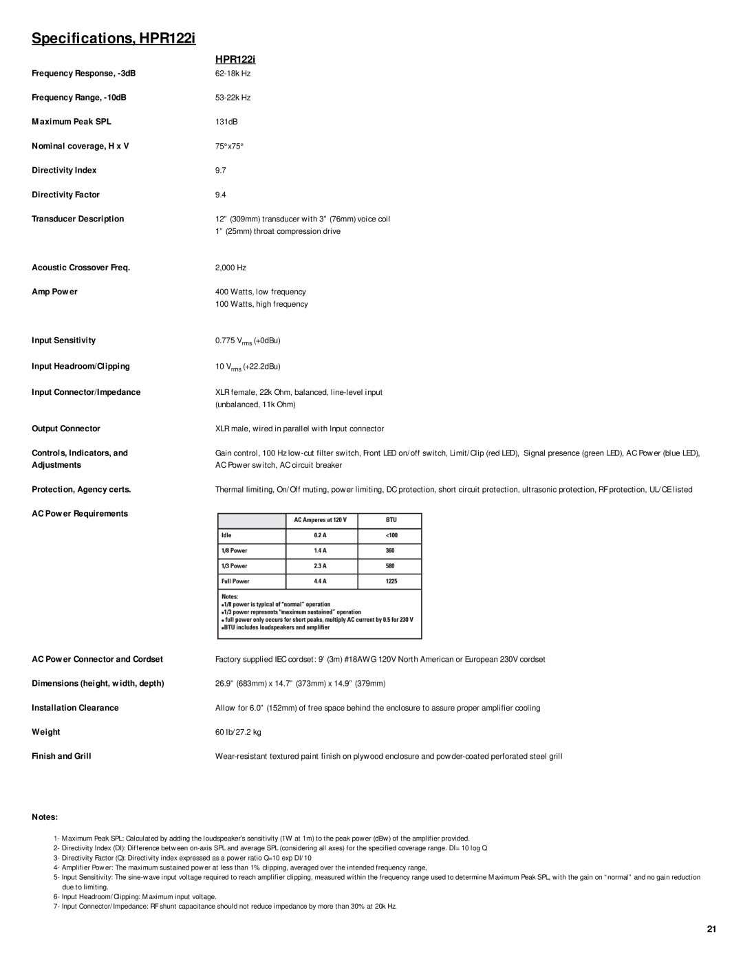
QSC Audio is renowned for delivering high-quality audio solutions, and their HPR series is a testament to this commitment. The HPR122i, HPR152i, HPR153i, HPR151i, and HPR181i are standout models in the lineup, catering to a variety of sound reinforcement needs.Starting with the HPR122i, this model is a 12-inch two-way loudspeaker designed for portable applications. It features a built-in 1000-watt Class D power amplifier, delivering exceptional clarity and high output. The rugged birch plywood enclosure enhances durability, while the advanced waveguide technology ensures a wide dispersion pattern, making it ideal for both live sound and permanent installations.
Moving up, the HPR152i showcases a larger 15-inch woofer, perfect for larger venues where deep bass and punchy sound are required. It retains the same robust build quality and integrated amplification as its smaller counterpart, ensuring reliability during extended use. The HPR152i’s contoured design allows for versatile positioning, whether it's on stands or as a floor monitor.
The HPR153i takes it a step further, offering a three-way design for even greater fidelity. With a dedicated 15-inch woofer, a 6.5-inch midrange, and a 1-inch compression driver, the HPR153i delivers a rich and detailed sound across all frequencies. This model is especially favored in settings where clarity and precision are paramount, such as concert halls and theatres.
Not to be overlooked, the HPR151i is a powerful subwoofer that complements the full-range speakers in the HPR series. Its 15-inch driver, paired with a 1000-watt Class D amplifier, delivers deep, impactful bass, enhancing the overall sonic experience. The HPR151i is ideal for situations requiring enhanced low-frequency response, making it a great match for DJs and live performers.
Finally, the HPR181i subwoofer elevates the low-end even further with its 18-inch woofer. This model is designed for serious bass enthusiasts, providing thunderous lows that can fill large spaces. Its robust design and advanced thermal management allow for extended use without overheating.
All models in the HPR series incorporate QSC’s Digital Signal Processing (DSP) technology, ensuring optimal sound performance and system protection. With their rugged construction, advanced features, and powerful sound, the QSC HPR series stands out as a top choice for audio professionals seeking reliability and exceptional performance in live sound applications. Whether for music, speech, or multimedia, the HPR series effectively meets the demands of diverse sound environments.