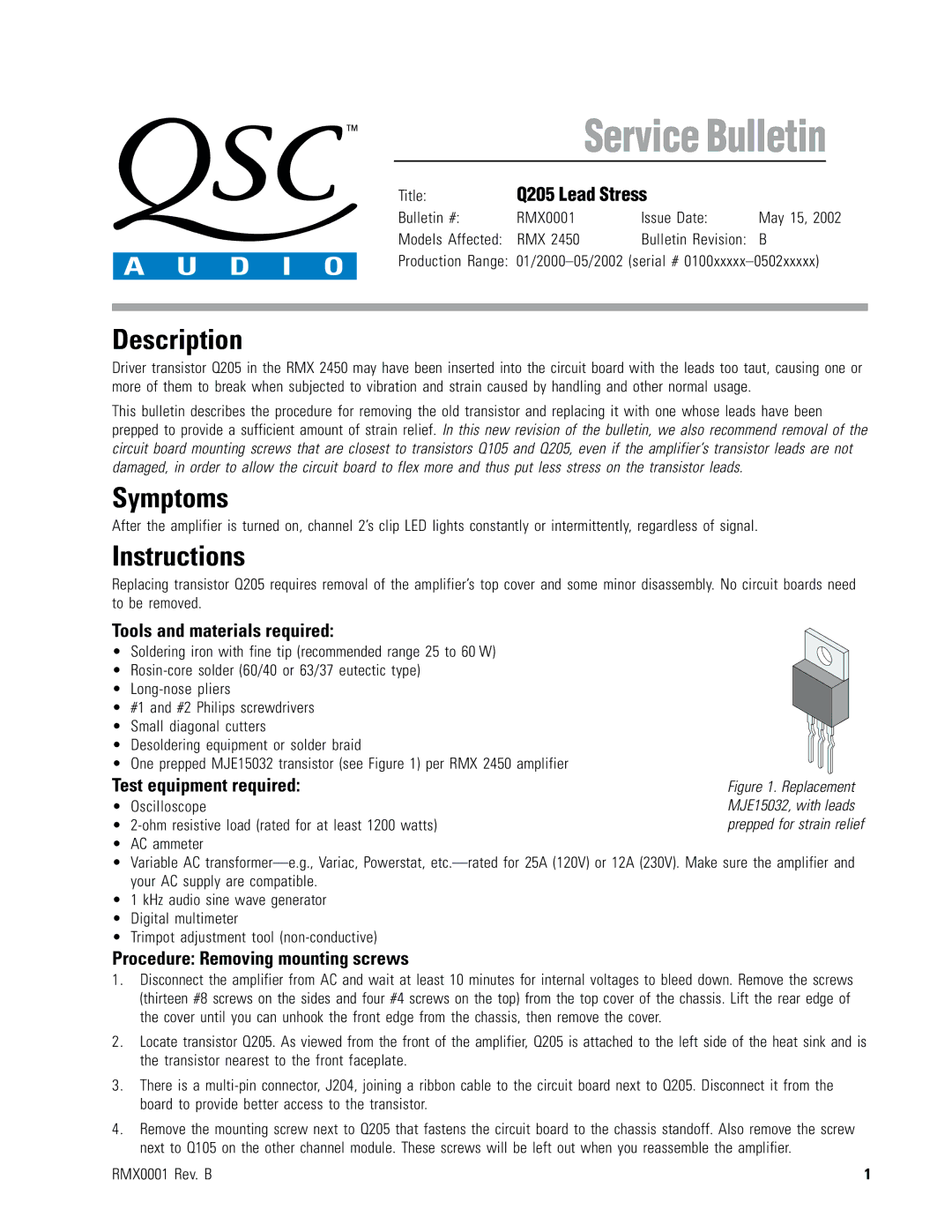
Figure 1. Replacement MJE15032, with leads prepped for strain relief

Service Bulletin

Title:

Q205 Lead Stress


Bulletin #:

RMX0001

Issue Date:

May 15, 2002

Models Affected:

RMX 2450

Bulletin Revision:

B

Production Range: 01/2000–05/2002 (serial # 0100xxxxx–0502xxxxx)

Description

Driver transistor Q205 in the RMX 2450 may have been inserted into the circuit board with the leads too taut, causing one or more of them to break when subjected to vibration and strain caused by handling and other normal usage.

This bulletin describes the procedure for removing the old transistor and replacing it with one whose leads have been prepped to provide a sufficient amount of strain relief. In this new revision of the bulletin, we also recommend removal of the circuit board mounting screws that are closest to transistors Q105 and Q205, even if the amplifier’s transistor leads are not damaged, in order to allow the circuit board to flex more and thus put less stress on the transistor leads.

Symptoms

After the amplifier is turned on, channel 2’s clip LED lights constantly or intermittently, regardless of signal.

Instructions

Replacing transistor Q205 requires removal of the amplifier’s top cover and some minor disassembly. No circuit boards need to be removed.

Tools and materials required:

• Soldering iron with fine tip (recommended range 25 to 60 W)

Rosin-core solder (60/40 or 63/37 eutectic type)

Long-nose pliers

#1 and #2 Philips screwdrivers

• Small diagonal cutters

Desoldering equipment or solder braid

One prepped MJE15032 transistor (see Figure 1) per RMX 2450 amplifier

Test equipment required:

• Oscilloscope

2-ohm resistive load (rated for at least 1200 watts)

AC ammeter

Variable AC transformer—e.g., Variac, Powerstat, etc.—rated for 25A (120V) or 12A (230V). Make sure the amplifier and your AC supply are compatible.

1 kHz audio sine wave generator

Digital multimeter

Trimpot adjustment tool (non-conductive)

Procedure: Removing mounting screws

1. Disconnect the amplifier from AC and wait at least 10 minutes for internal voltages to bleed down. Remove the screws (thirteen #8 screws on the sides and four #4 screws on the top) from the top cover of the chassis. Lift the rear edge of the cover until you can unhook the front edge from the chassis, then remove the cover.

2. Locate transistor Q205. As viewed from the front of the amplifier, Q205 is attached to the left side of the heat sink and is the transistor nearest to the front faceplate.

3. There is a multi-pin connector, J204, joining a ribbon cable to the circuit board next to Q205. Disconnect it from the board to provide better access to the transistor.

4. Remove the mounting screw next to Q205 that fastens the circuit board to the chassis standoff. Also remove the screw next to Q105 on the other channel module. These screws will be left out when you reassemble the amplifier.

RMX0001 Rev. B

1

Page 1
Image 1
QSC Audio Q205 manual Description, Symptoms, Instructions

Q205 specifications

The QSC Audio Q205 is a versatile and powerful audio interface designed for musicians and audio professionals seeking high-quality sound and reliable performance. This system is a part of QSC's renowned product lineup, known for its exceptional audio solutions that cater to both live sound and studio applications.

One of the defining features of the Q205 is its advanced audio technology. It includes high-resolution analog-to-digital and digital-to-analog converters, ensuring crystal-clear sound reproduction across a wide frequency range. This makes it an ideal choice for recording, mixing, and live sound reinforcement. With low latency performance, the Q205 allows musicians and sound engineers to interact seamlessly with their software and hardware setups.

The interface is equipped with multiple inputs and outputs, making it a flexible option for various audio setups. It features a combination of XLR and TRS inputs, accommodating a wide range of microphones and instruments. This versatility enables users to connect everything from vocal microphones to electric guitars, enhancing the Q205’s usability in different scenarios.

One of the most notable characteristics of the Q205 is its intuitive user interface. The front-panel controls are designed for easy access and navigation, allowing users to adjust settings on the fly without disrupting their workflow. The interface also comes equipped with LED indicators that provide real-time status updates on levels and connectivity, ensuring users are always in control of their sound.

In terms of build quality, the Q205 is constructed with durability in mind. The rugged chassis can withstand the rigors of both studio and live performance environments, making it a reliable choice for professionals who demand robustness in their equipment. Additionally, it features a compact design, which allows for easy portability and setup, whether on stage or in a studio.

The QSC Audio Q205 also supports high-quality audio over USB, enabling seamless integration with various digital audio workstations (DAWs). This feature simplifies the process of recording and mixing, making the workflow more efficient for users.

In summary, the QSC Audio Q205 stands out due to its combination of advanced audio technology, flexible connectivity, intuitive controls, and robust design. Whether you are a musician, sound engineer, or content creator, the Q205 delivers exceptional performance that meets the demands of modern audio production.