3OPERATING INSTRUCTIONS
This chapter presents detailed instructions on the operation of the 9700.
Overview
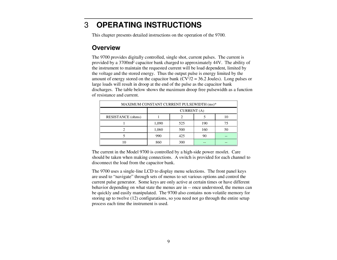
The 9700 provides digitally controlled, single shot, current pulses. The current is provided by a 3700mF capacitor bank charged to approximately 44V. The ability of the instrument to maintain the requested current will be load dependent, limited by the voltage and the stored energy. Thus the output pulse is energy limited by the amount of energy stored on the capacitor bank (CV2/2 = 36.2 Joules). Long pulses or large loads will result in droop at the end of the pulse as the capacitor bank discharges. The table below shows the maximum droop free pulsewidth as a function of resistance and current.
MAXIMUM CONSTANT CURRENT PULSEWIDTH (ms)*
|
| CURRENT (A) |
| |
RESISTANCE (ohms) | 1 | 2 | 5 | 10 |
|
|
|
|
|
1 | 1,090 | 525 | 190 | 75 |
|
|
|
|
|
2 | 1,060 | 500 | 160 | 50 |
|
|
|
|
|
5 | 990 | 425 | 90 | |
10 | 860 | 300 | ||
The current in the Model 9700 is controlled by a
The 9700 uses a
9