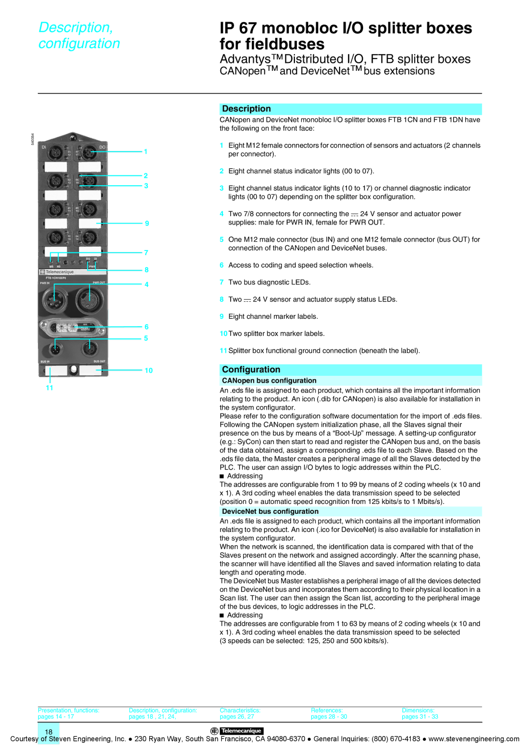
Splitter Boxes specifications
Quantum Instruments Splitter Boxes represent a significant advancement in the realm of optical signal processing and distribution. These sophisticated devices are designed to efficiently split and manage optical signals while ensuring minimal loss and optimal performance. One of the standout features of Quantum Instruments Splitter Boxes is their robust construction, which is designed to withstand harsh environmental conditions, making them suitable for both indoor and outdoor applications.A key technology utilized in these splitter boxes is the advanced fiber optic splitting technology, which employs high-quality optical fibers to achieve precise signal distribution. This technology allows for uniform splitting ratios, ensuring that each output maintains the integrity of the original signal. Furthermore, Quantum Instruments has integrated low-loss components into their splitter boxes, which contribute to high transmission efficiency and reduced signal attenuation.
In terms of characteristics, Quantum Instruments Splitter Boxes are available in various configurations to meet diverse user needs. They support multiple input and output configurations, ranging from simple one-to-two splits to complex multi-channel setups. This versatility makes them ideal for a wide range of applications, from telecommunications and data centers to broadcasting and surveillance systems.
The boxes also feature user-friendly interfaces for easy installation and maintenance. Their modular design allows for straightforward scaling and customization, enabling users to adapt the system as their requirements evolve. Additionally, the splitter boxes are equipped with advanced diagnostics and monitoring capabilities to ensure optimal performance and quick identification of any potential issues.
Moreover, Quantum Instruments prioritizes energy efficiency in their designs. The splitter boxes are engineered to minimize power consumption while maximizing performance, making them a sustainable choice for modern optical networks.
Quantum Instruments Splitter Boxes not only embody cutting-edge technology but also emphasize reliability and practicality. With a commitment to innovation, they continue to set benchmarks in the industry, making them a preferred choice for professionals looking to enhance their optical signal distribution systems. Their combination of high-quality materials, advanced technology, and user-oriented design ensures that users receive unparalleled performance and value. As the demand for more efficient communication systems grows, Quantum Instruments remains at the forefront, delivering solutions that cater to the evolving needs of the industry.

