Description

IP 67 modular I/O splitter boxes


for fieldbuses


AdvantysDistributed I/O, FTM splitter boxes

1

12

2

10

11


Bus module FTM with cover

Description


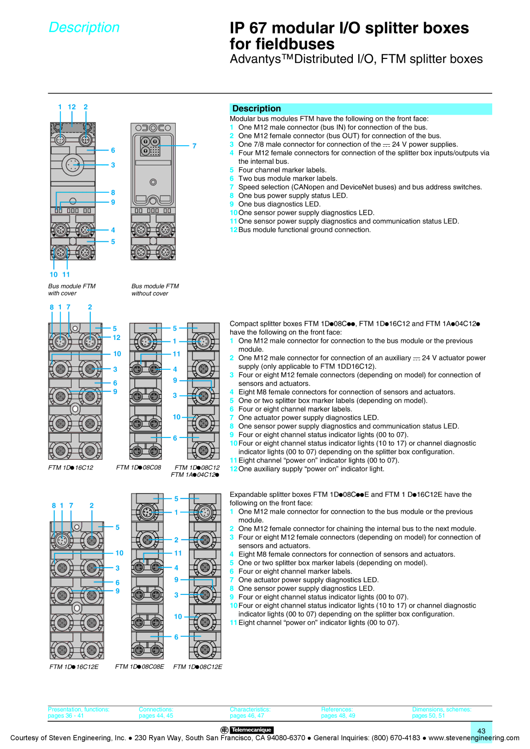
Modular bus modules FTM have the following on the front face:


1

One M12 male connector (bus IN) for connection of the bus.


2

One M12 female connector (bus OUT) for connection of the bus.

6


7

3

One 7/8 male connector for connection of the c 24 V power supplies.


4

Four M12 female connectors for connection of the splitter box inputs/outputs via


3


5

the internal bus.


Four channel marker labels.


6Two bus module marker labels.

7Speed selection (CANopen and DeviceNet buses) and bus address switches.

8

8

One bus power supply status LED.

9

9

One bus diagnostics LED.


10 One sensor power supply diagnostics LED.


11 One sensor power supply diagnostics and communication status LED.

4

12 Bus module functional ground connection.

5

Bus module FTM without cover

8

1

7

2

FTM 1Dp16C12


8 1

7


2


FTM 1Dp16C12E

5

5

12

1


10

11

3

4

6

9


9

3


10


6

FTM 1Dp08C08

FTM 1Dp08C12


FTM 1Ap04C12p


5


1

5


2

10

11

3

4

6

9


9

3


10


6

FTM 1Dp08C08E

FTM 1Dp08C12E

Compact splitter boxes FTM 1Dp08Cpp, FTM 1Dp16C12 and FTM 1Ap04C12p have the following on the front face:

1One M12 male connector for connection to the bus module or the previous module.

2One M12 male connector for connection of an auxiliary c 24 V actuator power supply (only applicable to FTM 1DD16C12).

3Four or eight M12 female connectors (depending on model) for connection of sensors and actuators.

4Eight M8 female connectors for connection of sensors and actuators.

5One or two splitter box marker labels (depending on model).

6Four or eight channel marker labels.

7One actuator power supply diagnostics LED.

8One sensor power supply diagnostics and communication status LED.

9Four or eight channel status indicator lights (00 to 07).

10Four or eight channel status indicator lights (10 to 17) or channel diagnostic indicator lights (00 to 07) depending on the splitter box configuration.

11Eight channel “power on” indicator lights (00 to 07).

12One auxiliary supply “power on” indicator light.

Expandable splitter boxes FTM 1Dp08CppE and FTM 1 Dp16C12E have the following on the front face:

1One M12 male connector for connection to the bus module or the previous module.

2One M12 female connector for chaining the internal bus to the next module.

3Four or eight M12 female connectors (depending on model) for connection of sensors and actuators.

4Eight M8 female connectors for connection of sensors and actuators.

5One or two splitter box marker labels (depending on model).

6Four or eight channel marker labels.

7One actuator power supply diagnostics LED.

8One sensor power supply diagnostics LED.

9Four or eight channel status indicator lights (00 to 07).

10Four or eight channel status indicator lights (10 to 17) or channel diagnostic indicator lights (00 to 07) depending on the splitter box configuration.

11Eight channel “power on” indicator lights (00 to 07).

Presentation, functions:

Connections:

Characteristics:

References:

Dimensions, schemes:

pages 36 - 41

pages 44, 45

pages 46, 47

pages 48, 49

pages 50, 51


43

Courtesy of Steven Engineering, Inc. ● 230 Ryan Way, South San Francisco, CA 94080-6370 ● General Inquiries: (800) 670-4183 ● www.stevenengineering.com

Page 43
Image 43
Quantum Instruments Splitter Boxes manual One bus power supply status LED

Splitter Boxes specifications

Quantum Instruments Splitter Boxes represent a significant advancement in the realm of optical signal processing and distribution. These sophisticated devices are designed to efficiently split and manage optical signals while ensuring minimal loss and optimal performance. One of the standout features of Quantum Instruments Splitter Boxes is their robust construction, which is designed to withstand harsh environmental conditions, making them suitable for both indoor and outdoor applications.

A key technology utilized in these splitter boxes is the advanced fiber optic splitting technology, which employs high-quality optical fibers to achieve precise signal distribution. This technology allows for uniform splitting ratios, ensuring that each output maintains the integrity of the original signal. Furthermore, Quantum Instruments has integrated low-loss components into their splitter boxes, which contribute to high transmission efficiency and reduced signal attenuation.

In terms of characteristics, Quantum Instruments Splitter Boxes are available in various configurations to meet diverse user needs. They support multiple input and output configurations, ranging from simple one-to-two splits to complex multi-channel setups. This versatility makes them ideal for a wide range of applications, from telecommunications and data centers to broadcasting and surveillance systems.

The boxes also feature user-friendly interfaces for easy installation and maintenance. Their modular design allows for straightforward scaling and customization, enabling users to adapt the system as their requirements evolve. Additionally, the splitter boxes are equipped with advanced diagnostics and monitoring capabilities to ensure optimal performance and quick identification of any potential issues.

Moreover, Quantum Instruments prioritizes energy efficiency in their designs. The splitter boxes are engineered to minimize power consumption while maximizing performance, making them a sustainable choice for modern optical networks.

Quantum Instruments Splitter Boxes not only embody cutting-edge technology but also emphasize reliability and practicality. With a commitment to innovation, they continue to set benchmarks in the industry, making them a preferred choice for professionals looking to enhance their optical signal distribution systems. Their combination of high-quality materials, advanced technology, and user-oriented design ensures that users receive unparalleled performance and value. As the demand for more efficient communication systems grows, Quantum Instruments remains at the forefront, delivering solutions that cater to the evolving needs of the industry.