Presentation (continued)

108387-25-M

530894

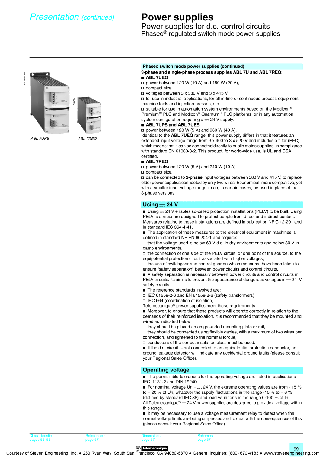
ABL 7UPS

ABL 7REQ

Characteristics:

References:

pages 55, 56

page 57

Power supplies

Power supplies for d.c. control circuits

Phaseo® regulated switch mode power supplies

Phaseo switch mode power supplies (continued)

3-phase and single-phase process supplies ABL 7U and ABL 7REQ:

bABL 7UEQ

vpower between 120 W (10 A) and 480 W (20 A), v compact size,

v voltages between 3 x 380 V and 3 x 415 V,

v for use in industrial applications, for all in-line or continuous process equipment,

machine tools and injection presses, etc.

v suitable for use in automation system environments based on the Modicon® PremiumPLC and Modicon® QuantumPLC platforms, or in any automation system configuration requiring a c 24 V supply.

b ABL 7UPS and ABL 7UES

v power between 120 W (5 A) and 960 W (40 A).

Identical to the ABL 7UEQ range, this power supply differs in that it features an extended input voltage range from 3 x 400 to 3 x 520 V and includes a filter (PFC) which means that it can be connected directly to public mains supplies, in compliance with standard EN 61000-3-2. This product, for world-wide use, is UL and CSA

certified.

b ABL 7REQ

v power between 120 W (5 A) and 240 W (10 A), v compact size,

v can be connected to 2-phaseinput voltages between 380 V and 415 V, to replace older power supplies connected by only two wires. Economical, more competitive, yet with a smaller input voltage range it can, in certain cases, be used in place of the 3-phase versions.

Using c 24 V

bUsing c 24 V enables so-called protection installations (PELV) to be built. Using PELV is a measure designed to protect people from direct and indirect contact. Measures relating to these installations are defined in publication NF C 12-201 and

in standard IEC 364-4-41.

b The application of these measures to the electrical equipment in machines is

defined in standard NF EN 60204-1 and requires:

v that the voltage used is below 60 V d.c. in dry environments and below 30 V in

damp environments,

v the connection of one side of the PELV circuit, or one point of the source, to the

equipotential protection circuit associated with higher voltages,

v the use of switchgear and control gear on which measures have been taken to

ensure "safety separation" between power circuits and control circuits.

b A safety separation is necessary between power circuits and control circuits in PELV circuits. Its aim is to prevent the appearance of dangerous voltages in c 24 V

safety circuits.

b The reference standards involved are:

v IEC 61558-2-6 and EN 61558-2-6 (safety transformers), v IEC 664 (coordination of isolation).

Telemecanique® power supplies meet these requirements.

b Moreover, to ensure that these products will operate correctly in relation to the demands of their reinforced isolation, it is recommended that they be mounted and

wired as indicated below:

v they should be placed on an grounded mounting plate or rail,

v they should be connected using flexible cables, with a maximum of two wires per

connection, and tightened to the nominal torque,

v conductors of the correct insulation class must be used.

b If the d.c. circuit is not connected to an equipotential protection conductor, an ground leakage detector will indicate any accidental ground faults (please consult your Regional Sales Office).

Operating voltage

bThe permissible tolerances for the operating voltage are listed in publications

IEC 1131-2 and DIN 19240.

b For nominal voltage Un = c 24 V, the extreme operating values are from - 15 % to + 20 % of Un, whatever the supply fluctuations in the range -10 % to + 6 %

(defined by standard IEC 38) and load variations in the range 0-100 % of In.

All Telemecanique® c 24 V power supplies are designed to provide a voltage within

this range.

b It may be necessary to use a voltage measurement relay to detect when the normal voltage limits are being surpassed and to deal with the consequences of this (please consult your Regional Sales Office).

Dimensions:

Schemes:

page 57

page 57

59

Courtesy of Steven Engineering, Inc. ● 230 Ryan Way, South San Francisco, CA 94080-6370 ● General Inquiries: (800) 670-4183 ● www.stevenengineering.com

Page 59
Image 59
Quantum Instruments Splitter Boxes manual Using c 24, Operating voltage, ABL 7UPS and ABL 7UES, ABL 7REQ

Splitter Boxes specifications

Quantum Instruments Splitter Boxes represent a significant advancement in the realm of optical signal processing and distribution. These sophisticated devices are designed to efficiently split and manage optical signals while ensuring minimal loss and optimal performance. One of the standout features of Quantum Instruments Splitter Boxes is their robust construction, which is designed to withstand harsh environmental conditions, making them suitable for both indoor and outdoor applications.

A key technology utilized in these splitter boxes is the advanced fiber optic splitting technology, which employs high-quality optical fibers to achieve precise signal distribution. This technology allows for uniform splitting ratios, ensuring that each output maintains the integrity of the original signal. Furthermore, Quantum Instruments has integrated low-loss components into their splitter boxes, which contribute to high transmission efficiency and reduced signal attenuation.

In terms of characteristics, Quantum Instruments Splitter Boxes are available in various configurations to meet diverse user needs. They support multiple input and output configurations, ranging from simple one-to-two splits to complex multi-channel setups. This versatility makes them ideal for a wide range of applications, from telecommunications and data centers to broadcasting and surveillance systems.

The boxes also feature user-friendly interfaces for easy installation and maintenance. Their modular design allows for straightforward scaling and customization, enabling users to adapt the system as their requirements evolve. Additionally, the splitter boxes are equipped with advanced diagnostics and monitoring capabilities to ensure optimal performance and quick identification of any potential issues.

Moreover, Quantum Instruments prioritizes energy efficiency in their designs. The splitter boxes are engineered to minimize power consumption while maximizing performance, making them a sustainable choice for modern optical networks.

Quantum Instruments Splitter Boxes not only embody cutting-edge technology but also emphasize reliability and practicality. With a commitment to innovation, they continue to set benchmarks in the industry, making them a preferred choice for professionals looking to enhance their optical signal distribution systems. Their combination of high-quality materials, advanced technology, and user-oriented design ensures that users receive unparalleled performance and value. As the demand for more efficient communication systems grows, Quantum Instruments remains at the forefront, delivering solutions that cater to the evolving needs of the industry.