2 Hardware Configuration
The DSCLP-200/300 is automatically configured at boot time by the computer's BIOS or operating system. There are no required switches or jumpers to set for installation.
This chapter lists a number of jumper settings that control various hardware features. Jumpers J1-J4, located in a column near the D-9 connectors, control the RS-422 or RS-485 signal line termination. Jumpers J5-J8, located in a column just to the right of J1-J4, control how signals are routed from the UARTs to the connector, as well as full- or half- duplex operation. Jumpers J10-J13, grouped together at the end of the board opposite the D-9 connectors, control special options.
Any changes from the factory default should be made before installing the DSCLP-200/300 in the computer.
2.1 RS-422 or RS-485 Signal Line Termination
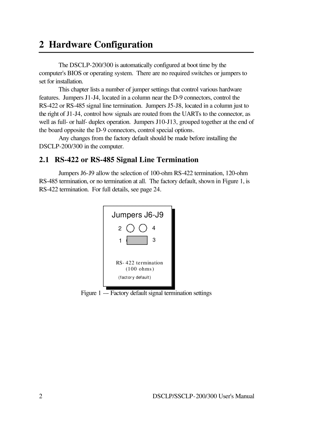
Jumpers J6-J9 allow the selection of 100-ohm RS-422 termination, 120-ohm RS-485 termination, or no termination at all. The factory default, shown in Figure 1, is RS-422 termination. For full details, see page 24.
Jumpers J6-J9
RS-422 termination (100 ohms)
(factory default)
Figure 1 --- Factory default signal termination settings
2 | DSCLP/SSCLP-200/300 User's Manual |