“FRONT PANEL”
OVERVIEW
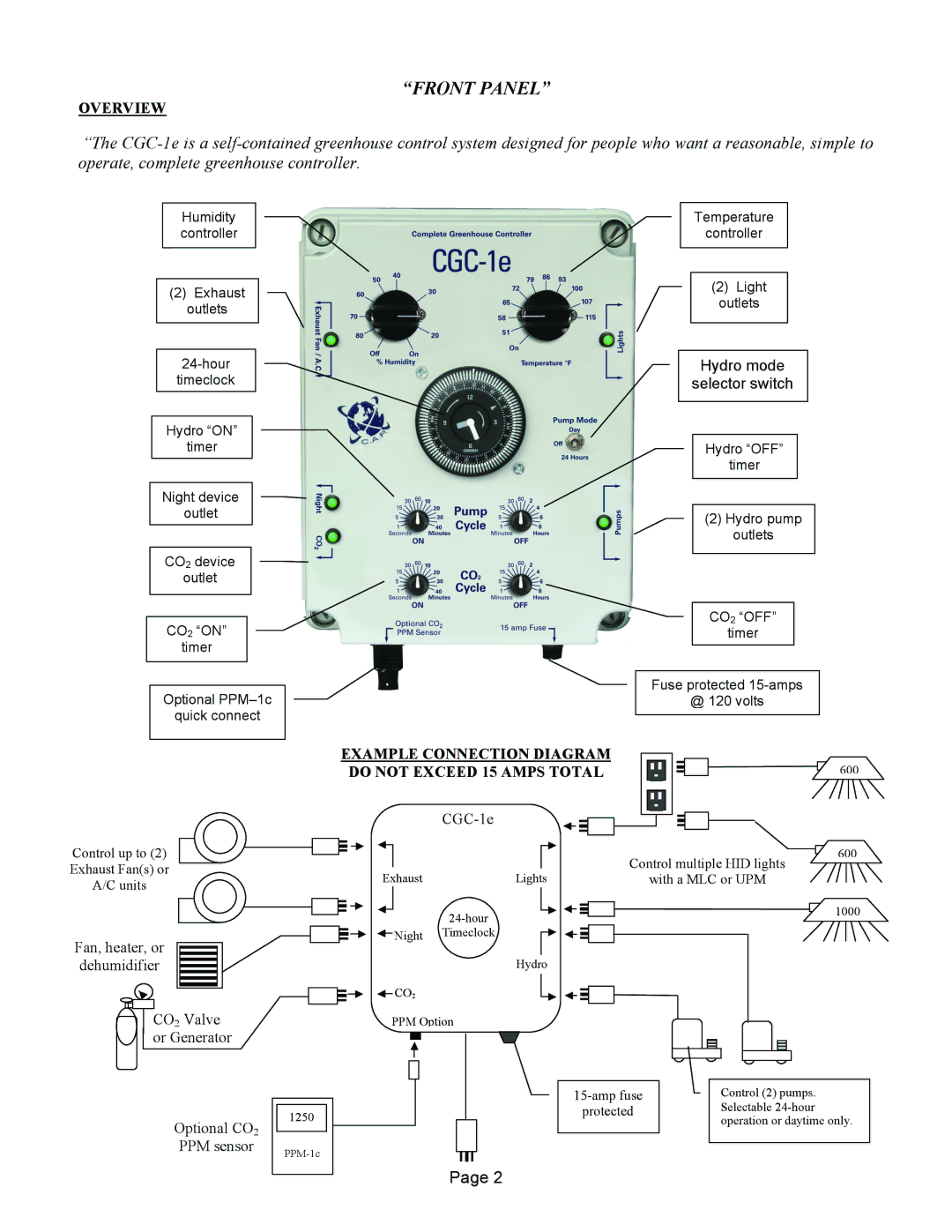
“The
Humidity controller
(2)Exhaust outlets
Hydro “ON”
Temperature
controller
(2)Light outlets
Hydro mode
selector switch
timer
Night device
outlet
CO2 device
outlet
CO2 “ON”
timer
Optional
quick connect
EXAMPLE CONNECTION DIAGRAM DO NOT EXCEED 15 AMPS TOTAL
CGC-1e
Hydro “OFF”
timer
(2)Hydro pump outlets
CO2 “OFF”
timer
Fuse protected
@ 120 volts
600
Control up to (2)
Exhaust Fan(s) or
A/C units
Fan, heater, or
dehumidifier
CO2 Valve or Generator
|
|
|
|
Optional CO2 |
| 1250 |
|
|
|
| |
|
|
| |
PPM sensor |
| ||
|
| ||
|
|
|
|
|
|
|
|
|
|
|
|
|
|
| Control multiple HID lights | 6 | 00 | |
|
|
|
|
|
|
|
|
|
|
| ||||
|
|
|
|
|
|
|
|
|
|
|
|
| ||
Exhaust | Lights |
|
|
| ||||||||||
| with a MLC or UPM |
|
| |||||||||||
|
|
| ||||||||||||
|
|
|
|
|
|
|
|
|
|
|
|
| 10 | 00 |
|
|
|
|
|
|
|
| |||||||
|
| Night | Timeclock |
|
|
|
|
|
|
|
| |||
|
|
|
|
|
|
|
|
|
|
|
|
| ||
|
|
|
|
|
|
|
|
|
|
|
|
| ||
|
|
|
|
|
|
|
|
|
|
|
|
|
|
|
Hydro
![]() CO2
CO2
PPM Option
Control (2) pumps. | |
protected | Selectable |
| operation or daytime only. |
Page 2
