6 | 5 | 7 | 3 | 10 |
English
2
19
8
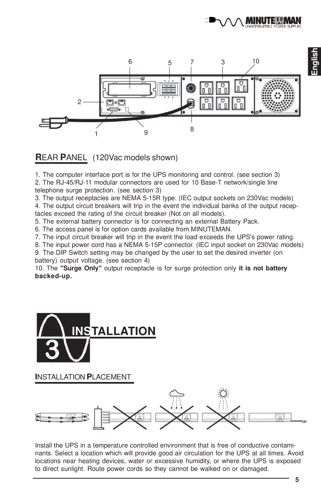
REAR PANEL (120Vac models shown)
1.The computer interface port is for the UPS monitoring and control. (see section 3)
2.The
3.The output receptacles are NEMA
4.The output circuit breakers will trip in the event the individual banks of the output recep- tacles exceed the rating of the circuit breaker (Not on all models).
5.The external battery connector is for connecting an external Battery Pack.
6.The access panel is for option cards available from MINUTEMAN.
7.The input circuit breaker will trip in the event the load exceeds the UPS's power rating.
8.The input power cord has a NEMA
9.The DIP Switch setting may be changed by the user to set the desired inverter (on battery) output voltage. (see section 4)
10.The "Surge Only" output receptacle is for surge protection only it is not battery
INSTALLATION
!
INSTALLATION PLACEMENT
Install the UPS in a temperature controlled environment that is free of conductive contami- nants. Select a location which will provide good air circulation for the UPS at all times. Avoid locations near heating devices, water or excessive humidity, or where the UPS is exposed to direct sunlight. Route power cords so they cannot be walked on or damaged.
5