49-454.fm Page 13 Wednesday, January 17, 2001 10:37 AM

Setting the Keypad’s Address

Note: If you connect only the supplied remote keypad to the alarm center, you do not need to set the keypad’s address.

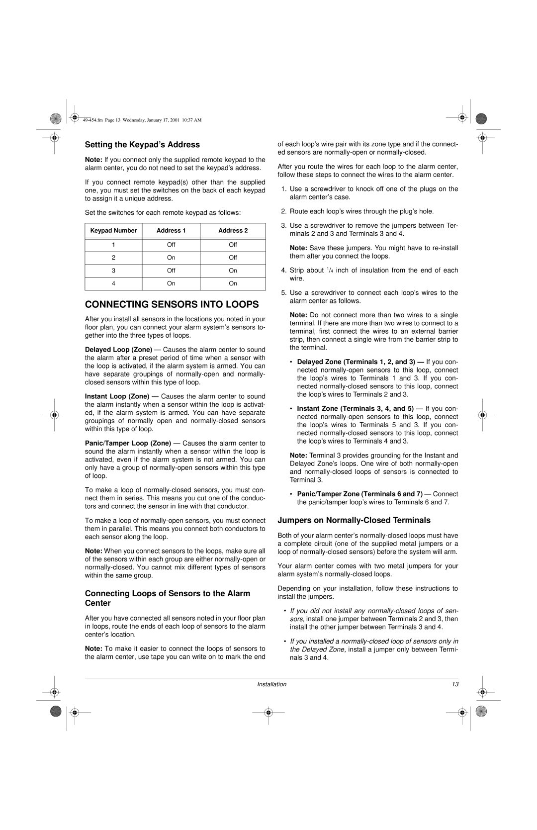
If you connect remote keypad(s) other than the supplied one, you must set the switches on the back of each keypad to assign it a unique address.

Set the switches for each remote keypad as follows:

Keypad Number

Address 1

Address 2


1

Off

Off


2

On

Off


3

Off

On


4

On

On


CONNECTING SENSORS INTO LOOPS

After you install all sensors in the locations you noted in your floor plan, you can connect your alarm system’s sensors to- gether into the three types of loops.

Delayed Loop (Zone) — Causes the alarm center to sound the alarm after a preset period of time when a sensor with the loop is activated, if the alarm system is armed. You can have separate groupings of normally-open and normally- closed sensors within this type of loop.

Instant Loop (Zone) — Causes the alarm center to sound the alarm instantly when a sensor within the loop is activat- ed, if the alarm system is armed. You can have separate groupings of normally open and normally-closed sensors within this type of loop.

Panic/Tamper Loop (Zone) — Causes the alarm center to sound the alarm instantly when a sensor within the loop is activated, even if the alarm system is not armed. You can only have a group of normally-open sensors within this type of loop.

To make a loop of normally-closed sensors, you must con- nect them in series. This means you cut one of the conduc- tors and connect the sensor in line with that conductor.

To make a loop of normally-open sensors, you must connect them in parallel. This means you connect both conductors to each sensor along the loop.

Note: When you connect sensors to the loops, make sure all of the sensors within each group are either normally-open or normally-closed. You cannot mix different types of sensors within the same group.

Connecting Loops of Sensors to the Alarm Center

After you have connected all sensors noted in your floor plan in loops, route the ends of each loop of sensors to the alarm center’s location.

Note: To make it easier to connect the loops of sensors to the alarm center, use tape you can write on to mark the end

of each loop’s wire pair with its zone type and if the connect- ed sensors are normally-open or normally-closed.

After you route the wires for each loop to the alarm center, follow these steps to connect the wires to the alarm center.

1.Use a screwdriver to knock off one of the plugs on the alarm center’s case.

2.Route each loop’s wires through the plug’s hole.

3.Use a screwdriver to remove the jumpers between Ter- minals 2 and 3 and Terminals 3 and 4.

Note: Save these jumpers. You might have to re-install them after you connect the loops.

4.Strip about 1/4 inch of insulation from the end of each wire.

5.Use a screwdriver to connect each loop’s wires to the alarm center as follows.

Note: Do not connect more than two wires to a single terminal. If there are more than two wires to connect to a terminal, first connect the wires to an external barrier strip, then connect a single wire from the barrier strip to the terminal.

Delayed Zone (Terminals 1, 2, and 3) — If you con- nected normally-open sensors to this loop, connect the loop’s wires to Terminals 1 and 3. If you con- nected normally-closed sensors to this loop, connect the loop’s wires to Terminals 2 and 3.

Instant Zone (Terminals 3, 4, and 5) — If you con- nected normally-open sensors to this loop, connect the loop’s wires to Terminals 5 and 3. If you con- nected normally-closed sensors to this loop, connect the loop’s wires to Terminals 4 and 3.

Note: Terminal 3 provides grounding for the Instant and Delayed Zone’s loops. One wire of both normally-open and normally-closed loops of sensors is connected to Terminal 3.

Panic/Tamper Zone (Terminals 6 and 7) — Connect the panic/tamper loop’s wires to Terminals 6 and 7.

Jumpers on Normally-Closed Terminals

Both of your alarm center’s normally-closed loops must have a complete circuit (one of the supplied metal jumpers or a loop of normally-closed sensors) before the system will arm.

Your alarm center comes with two metal jumpers for your alarm system’s normally-closed loops.

Depending on your installation, follow these instructions to install the jumpers.

If you did not install any normally-closed loops of sen- sors, install one jumper between Terminals 2 and 3, then install the other jumper between Terminals 3 and 4.

If you installed a normally-closed loop of sensors only in the Delayed Zone, install a jumper only between Termi- nals 3 and 4.

Installation

13


Page 13
Image 13
Radio Shack Two-Zone Burglar Alarm System owner manual Connecting Sensors Into Loops, Setting the Keypad’s Address

Two-Zone Burglar Alarm System specifications

The Radio Shack Two-Zone Burglar Alarm System is designed to provide homeowners and small business owners with effective security solutions. This system offers an excellent balance of functionality, reliability, and affordability, making it a popular choice for those looking to enhance their property's safety.

One of the standout features of the Radio Shack Two-Zone Burglar Alarm System is its dual-zone capability. This allows users to monitor multiple areas of their property separately. For example, one zone can be designated for exterior doors, while another can monitor interior spaces, which can help to prevent false alarms triggered by pets or other movements within the home. This feature is particularly useful for larger properties that require more than just a single-point monitoring system.

The system is equipped with multiple sensors, including door and window contacts, which can easily be installed to ensure comprehensive coverage. These sensors are designed to detect unauthorized entry and trigger the alarm whenever a door or window is opened. The system also includes passive infrared motion sensors that can identify movement within a designated area, adding an additional layer of security against intruders.

In terms of technologies, the Radio Shack Two-Zone Burglar Alarm System utilizes a microprocessor-controlled control panel, which is at the heart of the system's operations. This logic board processes signals from all connected sensors and determines when to trigger the alarm. The system can provide alerts via a loud siren, while also allowing for notifications to be sent to the owner’s smartphone or other devices, depending on the model.

The installation process for the Radio Shack burglar alarm system is user-friendly, designed for ease even for those who may not be technically savvy. The system typically includes clear instructions and mounting hardware, making setup straightforward. Users can customize their alarm system according to their specific needs and property layout, which further enhances usability.

Another important characteristic of the Radio Shack Two-Zone Burglar Alarm System is the option for battery backup. This ensures that the alarm continues to operate even during power outages, allowing for uninterrupted security coverage. Moreover, the system is frequently praised for its durability and resistance to environmental factors, making it a robust choice for various settings.

Overall, the Radio Shack Two-Zone Burglar Alarm System represents a practical and efficient security solution, combining essential features, advanced technology, and user-friendly installation, all designed to meet the security needs of modern users.