rrw1b specifications
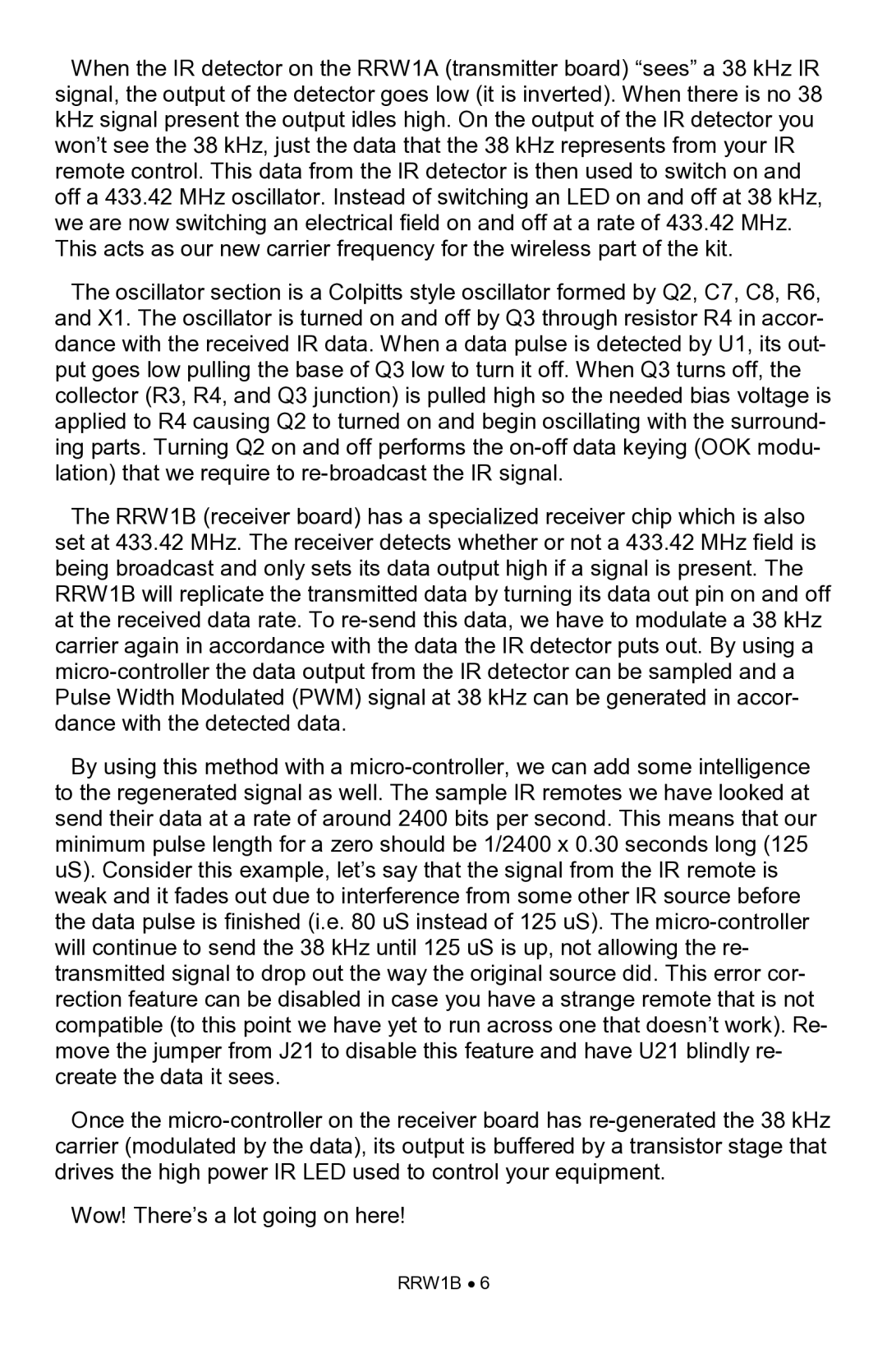
The Ramsey Electronics RRW1B is a versatile and compact wireless transmitter and receiver system designed for various applications, including remote control and communications. This innovative device operates on the 27 MHz band, offering a robust solution for users seeking reliable wireless connectivity. One of the standout features of the RRW1B is its impressive transmission range, allowing for operation up to 1000 feet under optimal conditions. This makes it suitable for both hobbyist projects and professional applications where distance and reliability are critical.The RRW1B utilizes frequency modulation (FM) technology, which ensures clear signal transmission and minimal interference from other devices operating on similar frequencies. Its design incorporates advanced circuitry that enhances its performance, contributing to a stable link between the transmitter and receiver while effectively reducing noise. This technology is particularly beneficial for applications in remote sensing, data logging, and control systems where accuracy is paramount.
Another notable characteristic of the RRW1B is its user-friendly interface, which allows for easy setup and configuration. The system is designed with the end-user in mind, featuring color-coded terminals and intuitive controls that facilitate straightforward installation. This aspect makes it accessible to both beginners and experienced technicians, reducing the learning curve typically associated with wireless systems.
The RRW1B is also characterized by its low power consumption, making it an energy-efficient choice for long-term use. This is particularly advantageous for battery-operated devices, extending their operational lifespan and reducing the frequency of battery replacements. Moreover, the RF (radio frequency) modules used in the RRW1B are known for their durability and resilience, ensuring that users can rely on the system in various environments, including those with challenging electromagnetic conditions.
In summary, the Ramsey Electronics RRW1B stands out due to its excellent range, FM technology, ease of use, and energy efficiency. These features make it a popular choice among hobbyists and professionals alike, providing a seamless wireless solution for a myriad of applications. Whether users are looking to enhance their home automation systems, develop remote-control gadgets, or implement wireless data communication, the RRW1B proves to be a capable and dependable option. Its combination of performance, simplicity, and versatility makes it a valuable addition to the toolkit of anyone interested in electronics and wireless technology.
