IMPORTANT: Table is coated with a protectant. To ensure proper fit and operation, remove coating. Coating is easily removed with mild solvents, such as mineral spirits, and a soft cloth. Avoid getting solution on paint or any of the rubber or plastic parts. Solvents may deteriorate these finishes. Use soap and water on paint, plastic or rubber components. After cleaning, cover all exposed surfaces with a light coating of oil. Paste wax is recommended for table top.
WARNING: Never use highly volatile solvents. Non flamma- ble solvents are recommended to avoid possible fire hazard.
ASSEMBLY
Refer to Figures
CAUTION: Do not attempt assembly if parts are missing. Use this manual to order replacement parts.
Be certain all parts are clean and free of shipping preserva- tive. Also, completely remove all parts of packing. Saw cabinet should be directly on the floor.
SAW INSTALLATION
Positioning the saw on a level surface will improve stability and accuracy and prevent warpage and failure of cast components and welds.
WARNING: Make certain that the saw is disconnected from the power source.
INSTALL HANDWHEELS
Refer to Figure 3.
¥Remove saw cabinet and place upside down on cardboard box or cardboard on floor.
¥Place one of the handwheels onto the blade raise/lower shaft located on the front of the cabinet. Align the groove in the back of the handwheel with the pin.
¥Thread the washer and locking knob onto the threaded end of the shaft.
¥Repeat the steps above to assemble the remaining hand- wheel and locking knob onto the blade tilt shaft located on the side of the cabinet.
Blade Raise Handwheel
Blade Tilt
Handwheel
Figure 3
REMOVE PACKING MATERIAL
Refer to Figure 4.
¥Use the blade tilt handwheel to tilt the motor completely to 45¡.
¥Remove the packing material from behind the motor.
¥Return motor to the 0¡ position.
Remove this packing material
Figure 4
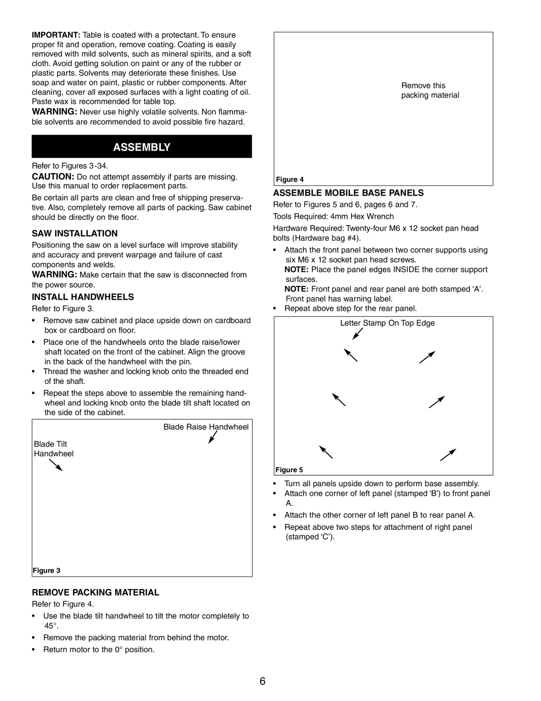
ASSEMBLE MOBILE BASE PANELS
Refer to Figures 5 and 6, pages 6 and 7. Tools Required: 4mm Hex Wrench
Hardware Required:
¥Attach the front panel between two corner supports using six M6 x 12 socket pan head screws.
NOTE: Place the panel edges INSIDE the corner support surfaces.
NOTE: Front panel and rear panel are both stamped ÔAÕ. Front panel has warning label.
¥Repeat above step for the rear panel.
Letter Stamp On Top Edge
Figure 5
¥Turn all panels upside down to perform base assembly.
¥Attach one corner of left panel (stamped ÔBÕ) to front panel A.
¥Attach the other corner of left panel B to rear panel A.
¥Repeat above two steps for attachment of right panel (stamped ÔCÕ).
6