Rip Fence Dimensions:
Rip fence . . . . . . . . . . . . . . . . . . . . . . . . . . . . . . . . . . . . . 311Ú4″ Rip fence rails (front and rear) . . . . . . . . . . . . . . . . . . . . . 561Ú2″ Blade capacity maximum . . . . . . . . . . . . . . . . . . . . . . . . . . 10″ Blade arbor . . . . . . . . . . . . . . . . . . . . . . . . . . . . . . . . . . . . . 5Ú8″ Dado blade capacity maximum . . . . . . . . . . . . . . . . . . . . . 13Ú16″
Saw Constructions:
Cabinet . . . . . . . . . . . . . . . . . . . . Totally enclosed steel panel Table . . . . . . . . . . . . . . . . . . . . . . . . . . . . . . . . . . . . . Cast iron Rip fence . . . . . . . . . . . . . . . . . . . . . . . . . . . . . Aluminum tube Drive system . . . . . . . . . . . . . . . . . . . . . . . . . . . . . . . . . .
capacitor run, 120/240V, 15/7.5A,
Gross weight with motor . . . . . . . . . . . . . . . . . . . . . . . 288 lbs
WARNING: Disconnect power before attempting any of the following procedures. Be certain switch is in OFF position and safety disconnect (or breaker) is in OFF or open position. Saw blade must not be moving. Saw blade will rotate freely after motor is turned off. Allow blade to come to a complete stop before attempting any of the following procedures.
WARNING: The operation of any power tool can result in foreign objects being thrown into the eyes, which can result in severe eye damage. Always wear safety goggles complying with United States ANSI Z87.1 before commencing power tool operation.
STARTING AND STOPPING THE SAW
Refer to Figure 43.
WARNING: Never operate saw without blade guards in place. Be sure blade is not in contact with workpiece when motor is started. Start motor and allow saw to come to full speed.
WARNING: Make sure the electrical characteristics of motor nameplate and power source are the same.
¥The ON/OFF switch is located under the front rail of the table saw at the left side.
¥To turn saw on, stand to either side of the bladeÑnever in line with it. Raise large red OFF paddle and pull up ON/OFF switch. Always allow saw blade to come up to full speed before cutting.
¥Do not turn motor switch ON and OFF rapidly. This action overheats the motor and may cause saw blade to loosen.
¥Never leave saw while the power is on.
¥To turn the table saw off, press the large red OFF paddle. Never leave saw until cutting tool has come to a complete stop.
The saw can be locked from unauthorized use by locking the switch. To lock the switch:
¥Turn the switch to OFF position and disconnect saw from power source.
¥Pull the key out. The switch cannot be turned on with the key removed.
NOTE: Should the key be removed from the switch at the ON position, the switch can be turned off but cannot be turned on again.
¥To replace key, slide key into the slot on switch until it snaps.
WARNING: For your own safety, lower blade or cutting tool below table surface. If blade is tilted, return it to vertical posi- tion. Turn off safety disconnect or circuit breaker when saw is not in use.
Paddle
Key![]()
Switch
Figure 43 - ON/OFF Switch
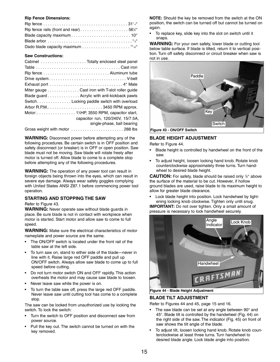
BLADE HEIGHT ADJUSTMENT
Refer to Figure 44.
¥Blade height is controlled by handwheel on the front of the saw.
¥To adjust height, loosen locking hand knob. Rotate knob counterclockwise approximately three turns. Turn hand- wheel to desired blade height.
CAUTION: For safety, blade should be raised only 1/8″ above the surface of the material to be cut. However, if hollow ground blades are used, raise blade to its maximum height to allow for greater blade clearance.
¥Lock blade height into position. Lock handwheel by tight- ening locking knob clockwise. Tighten only until snug.
IMPORTANT: Do not over tighten. Only a small amount of pressure is necessary to lock handwheel securely.
Angle | Lock Knob | |
Indicator | ||
|
Handwheel ![]()
Figure 44 - Blade Height Adjustment
BLADE TILT ADJUSTMENT
Refer to Figures 44 and 45, page 15 and 16.
¥The saw blade can be set at any angle between 90¡ and 45¡. Blade tilt is controlled by the handwheel (Fig. 44) on the right side of the saw. The indicator (Fig. 45) on front of saw shows the tilt angle of the blade.
¥To adjust tilt, loosen locking hand knob. Rotate knob coun- terclockwise at least three turns. Turn handwheel to desired blade angle. Lock blade angle into position.
15