¥Make sure locking pin is aligned with riving knife hole and secure in position by tightening locking knob.
¥Riving knife must be in line with blade. Make sure riving knife sits flat against mounting bracket and lock plate.
RIVING KNIFE TO BLADE ADJUSTMENT
¥Riving knife to blade clearance: the gap between the riving knife and the saw blade should be an even distance across the entire radius.
¥The riving knife should also be in line with the saw blade. If adjustment is necessary:
1.Locate the riving knife bracket.
2.Loosen the two socket head cap screws slightly enough to move the bracket, bringing the riving knife in line with the saw blade. Make sure the gap between the blade and knife is even and from 1Ú4 to 5Ú16″ in distance.
3.Once the riving knife is aligned with the blade, tighten the socket head cap screws.
INSTALL TABLE INSERT
Refer to Figure 32.
¥Make sure that the riving knife is raised to its highest position.
¥Place table insert into throat of table.
¥Insert is held in position by magnet in table.
¥To adjust insert level with table, adjust leveling screws up or down.
Leveling Screws
Figure 32
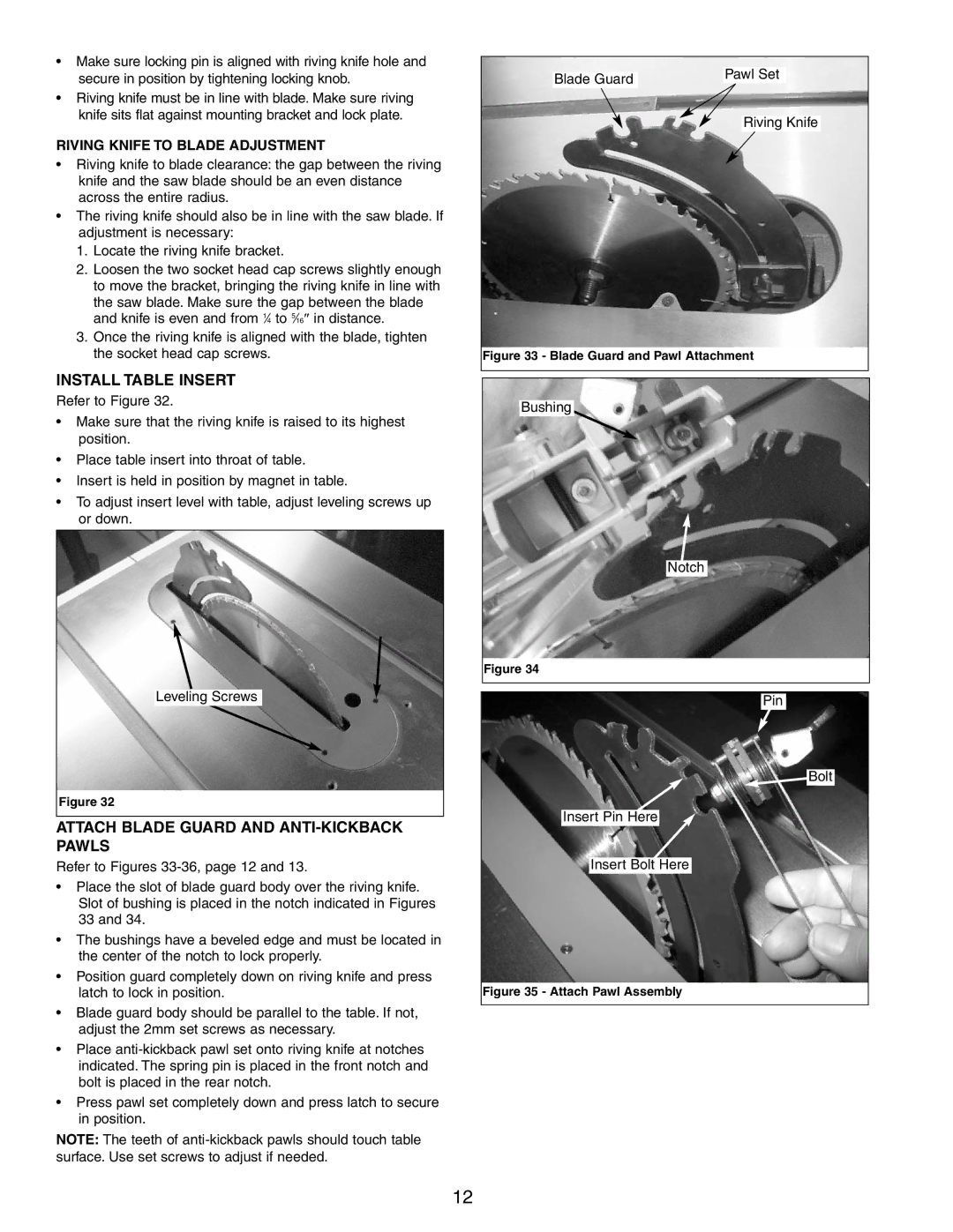
ATTACH BLADE GUARD AND ANTI-KICKBACK PAWLS
Refer to Figures
¥Place the slot of blade guard body over the riving knife. Slot of bushing is placed in the notch indicated in Figures 33 and 34.
¥The bushings have a beveled edge and must be located in the center of the notch to lock properly.
¥Position guard completely down on riving knife and press latch to lock in position.
¥Blade guard body should be parallel to the table. If not, adjust the 2mm set screws as necessary.
¥Place
¥Press pawl set completely down and press latch to secure in position.
NOTE: The teeth of
|
|
| |
|
| Pawl Set | |
Blade Guard | |||
|
|
Riving Knife
Figure 33 - Blade Guard and Pawl Attachment
Bushing
Notch
Figure 34
Pin
![]() Bolt
Bolt
Insert Pin Here
Insert Bolt Here
Figure 35 - Attach Pawl Assembly
12