Figure 26 - Check parallelism of rails to table with combination square. Check at several locations along rail.
¥Loosen and remove six socket pan head screws and the back panel. This will allow easier attachment of the rear rails.
Figure 27
¥Install the rear rails in the same manner as the front rails and align the rail joint to the blade.
¥Replace back panel of the cabinet.
Figure 28
¥Insert M8 x 20 hex bolts through holes in bracket at each end of brace. Attach brace to the far right end of the rails by sliding hex bolts into the rail
Figure 29
ATTACH SWITCH ASSEMBLY
Refer to Figure 30.
Tools Required: 10mm Open end Wrench
Hardware Required: Two M6 x 16 hex head bolts, two M6 flat washers, two M6 lock washers and two M6 hex nuts. (Hardware bag #3).
¥From above switch assembly bracket, insert two bolts through bracket holes.
¥Loosely attach flat washer, lock washer and nut to bolts.
¥Insert bolt heads into
¥Slide switch assembly 6″ to 8″ from left end of rail as shown in Figure 30.
¥Fully tighten flat washers, lock washers and hex nuts to secure switch assembly in place.
Figure 30
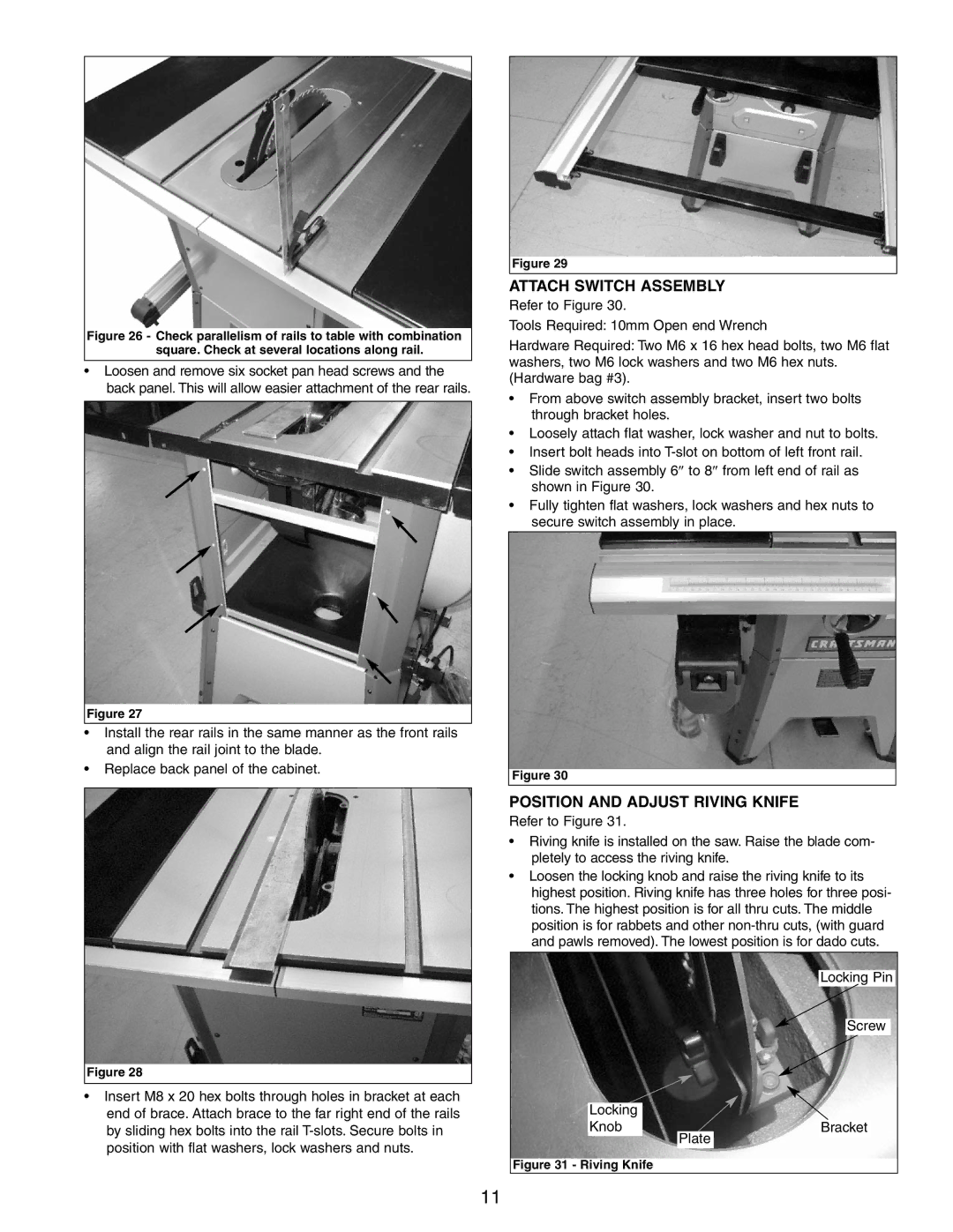
POSITION AND ADJUST RIVING KNIFE
Refer to Figure 31.
¥Riving knife is installed on the saw. Raise the blade com- pletely to access the riving knife.
¥Loosen the locking knob and raise the riving knife to its highest position. Riving knife has three holes for three posi- tions. The highest position is for all thru cuts. The middle position is for rabbets and other
Locking Pin
Screw
Locking |
|
|
|
|
Knob |
|
|
|
|
|
| Bracket | ||
Plate |
| |||
|
|
|
|
Figure 31 - Riving Knife
11