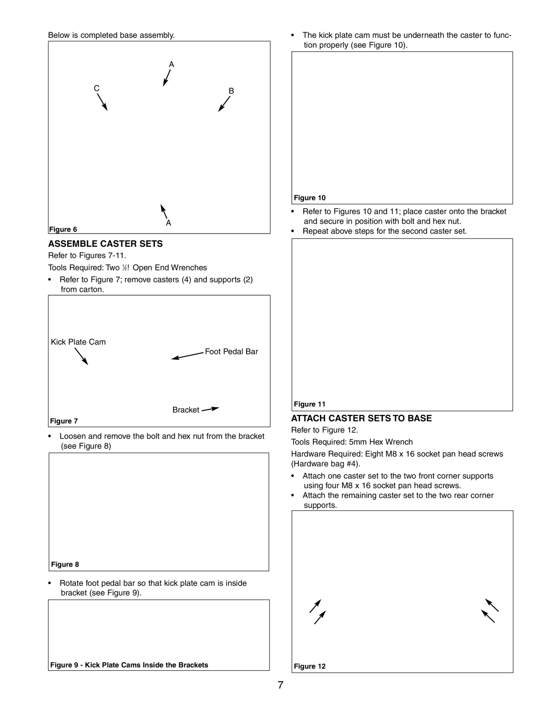
Below is completed base assembly.
A
C | B |
|
¥The kick plate cam must be underneath the caster to func- tion properly (see Figure 10).
Figure 10
Figure 6
A
¥Refer to Figures 10 and 11; place caster onto the bracket and secure in position with bolt and hex nut.
¥Repeat above steps for the second caster set.
ASSEMBLE CASTER SETS
Refer to Figures
Tools Required: Two 1Ú2″ Open End Wrenches
¥Refer to Figure 7; remove casters (4) and supports (2) from carton.
Kick Plate Cam
Foot Pedal Bar
Bracket![]()
Figure 7
¥Loosen and remove the bolt and hex nut from the bracket (see Figure 8)
Figure 8
¥Rotate foot pedal bar so that kick plate cam is inside bracket (see Figure 9).
Figure 9 - Kick Plate Cams Inside the Brackets
Figure 11
ATTACH CASTER SETS TO BASE
Refer to Figure 12.
Tools Required: 5mm Hex Wrench
Hardware Required: Eight M8 x 16 socket pan head screws (Hardware bag #4).
¥Attach one caster set to the two front corner supports using four M8 x 16 socket pan head screws.
¥Attach the remaining caster set to the two rear corner supports.
Figure 12
7