¥If an adjustment is necessary, proceed as follows: Loosen and remove the six socket pan head screws and the rear panel (see Figure 22). Loosen the four hex head bolts on the trunnion (see Figure 23) and shift trunnions until a position is found where the saw blade is parallel to the miter guage slots.
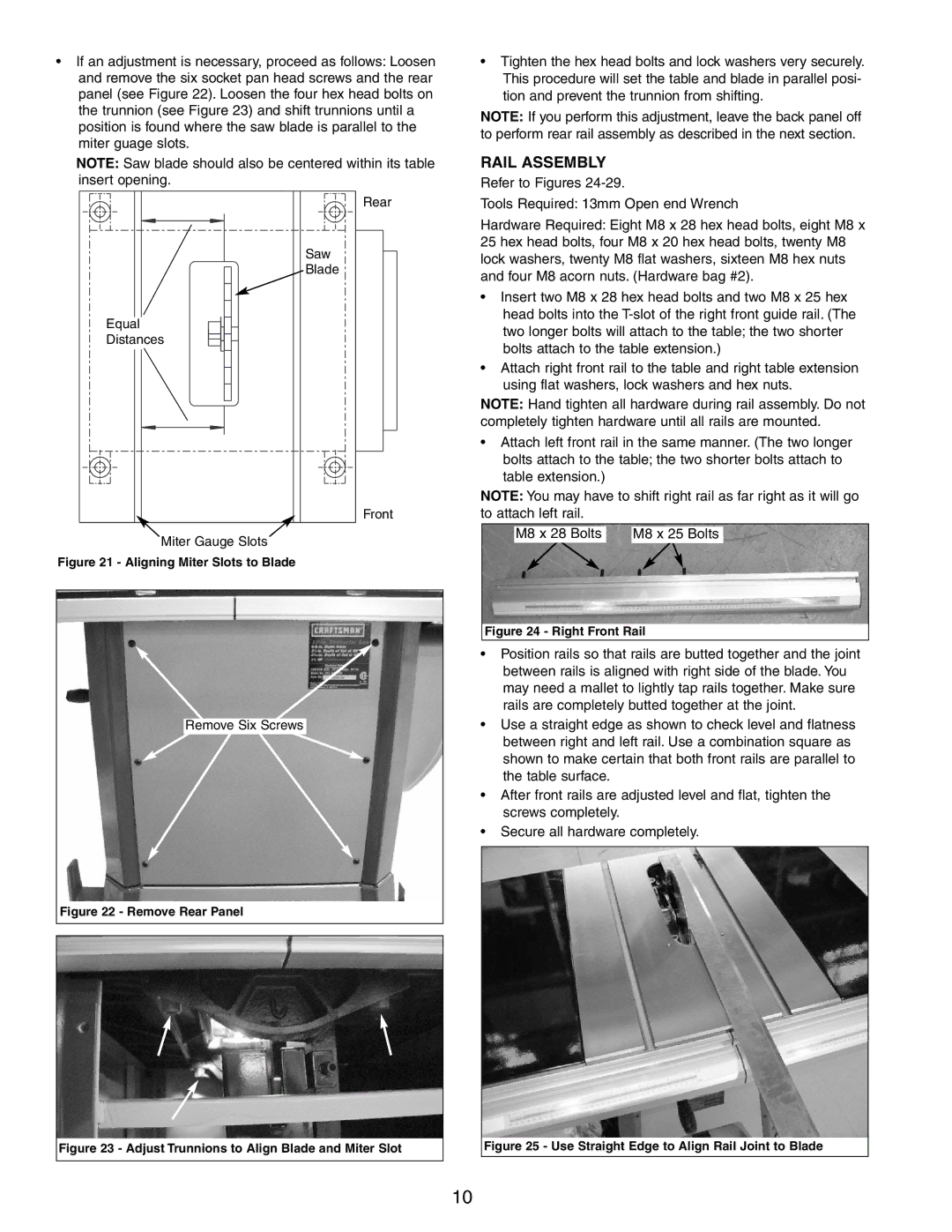
NOTE: Saw blade should also be centered within its table insert opening.
Rear
Saw
Blade
Equal
Distances
Front
Miter Gauge Slots
Figure 21 - Aligning Miter Slots to Blade
Remove Six Screws
Figure 22 - Remove Rear Panel
Figure 23 - Adjust Trunnions to Align Blade and Miter Slot
¥Tighten the hex head bolts and lock washers very securely. This procedure will set the table and blade in parallel posi- tion and prevent the trunnion from shifting.
NOTE: If you perform this adjustment, leave the back panel off to perform rear rail assembly as described in the next section.
RAIL ASSEMBLY
Refer to Figures
Tools Required: 13mm Open end Wrench
Hardware Required: Eight M8 x 28 hex head bolts, eight M8 x 25 hex head bolts, four M8 x 20 hex head bolts, twenty M8 lock washers, twenty M8 flat washers, sixteen M8 hex nuts and four M8 acorn nuts. (Hardware bag #2).
¥Insert two M8 x 28 hex head bolts and two M8 x 25 hex head bolts into the
¥Attach right front rail to the table and right table extension using flat washers, lock washers and hex nuts.
NOTE: Hand tighten all hardware during rail assembly. Do not completely tighten hardware until all rails are mounted.
¥Attach left front rail in the same manner. (The two longer bolts attach to the table; the two shorter bolts attach to table extension.)
NOTE: You may have to shift right rail as far right as it will go to attach left rail.
M8 x 28 Bolts |
|
|
| M8 x 25 Bolts |
Figure 24 - Right Front Rail
¥Position rails so that rails are butted together and the joint between rails is aligned with right side of the blade. You may need a mallet to lightly tap rails together. Make sure rails are completely butted together at the joint.
¥Use a straight edge as shown to check level and flatness between right and left rail. Use a combination square as shown to make certain that both front rails are parallel to the table surface.
¥After front rails are adjusted level and flat, tighten the screws completely.
¥Secure all hardware completely.
Figure 25 - Use Straight Edge to Align Rail Joint to Blade
10