Manuals
/
Raypak
/
Household Appliance
/
Boiler
Raypak
241275
manual
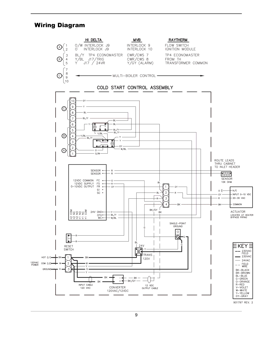
Wiring Diagram
Models:
241275
1
9
22
22
Download
22 pages
16.83 Kb
6
7
8
9
10
11
12
13
Troubleshooting
Install
Parts list
Wiring Diagram
START-UP Procedure
Safety
Mode Selection Switch
Page 9
Image 9
Wiring Diagram
9
Page 8
Page 10
Page 9
Image 9
Page 8
Page 10
Contents
Installation and Operating Instructions
Page
Time/Temperature Relationships in Scalds
General Safety
Cold Water Start
Installation
Operation
Connecting Power to the Controller
Cold Start Sequence Operation
Mode Selection Switch
Elodrive Actuator Rotation Knob Setting
Troubleshooting
Cold Water Start Troubleshooting Guide
Wiring Diagram
Cold Water RUN
Model Pump
Injection & Heater Pump Comparison Hi Delta
Before Starting
Injection Pump Cover Installation
Place the cover on the pump
Typical Boiler Piping Hi Delta shown
Sequence of Operation
START-UP Procedure
Wiring Diagram
Step
Cold Water Run Troubleshooting Guide
Cold Water Start
Illustrated Parts Lists
Call OUT Description HI Delta MVB
Cold Water Run
Call Description HI Delta MVB OUT
Top
Page
Image
Contents