2.Attach mounting angles to heater jacket with 1/2" sheet metal screws, (4 places).
Fig. 4: Location of Mounting Angles
3.Lower outdoor top to heater and secure with 1" sheet metal screws.
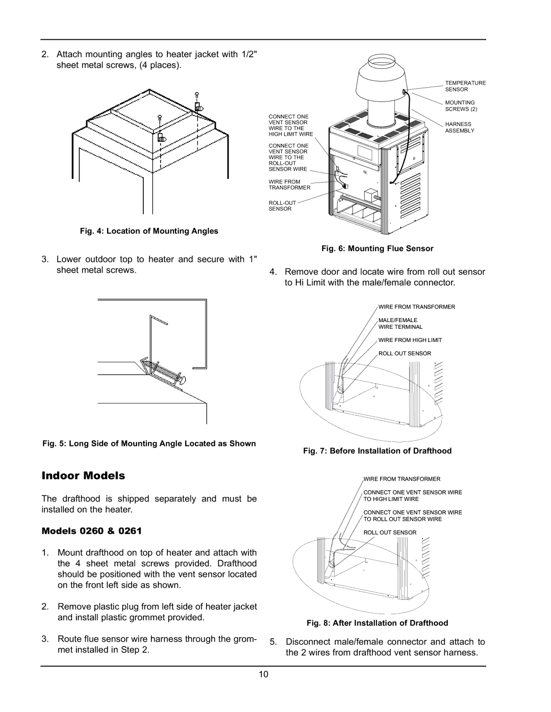
| TEMPERATURE | |
| SENSOR | |
| MOUNTING | |
| SCREWS (2) | |
CONNECT ONE |
| |
VENT SENSOR | HARNESS | |
WIRE TO THE | ||
ASSEMBLY | ||
HIGH LIMIT WIRE | ||
| ||
CONNECT ONE |
| |
VENT SENSOR |
| |
WIRE TO THE |
| |
| ||
SENSOR WIRE |
| |
WIRE FROM |
| |
TRANSFORMER |
| |
| ||
SENSOR |
|
Fig. 6: Mounting Flue Sensor
4.Remove door and locate wire from roll out sensor to Hi Limit with the male/female connector.
WIRE FROM TRANSFORMER
MALE/FEMALE
WIRE TERMINAL
WIRE FROM HIGH LIMIT
ROLL OUT SENSOR
Fig. 5: Long Side of Mounting Angle Located as Shown
Indoor Models
The drafthood is shipped separately and must be installed on the heater.
Models 0260 & 0261
1.Mount drafthood on top of heater and attach with the 4 sheet metal screws provided. Drafthood should be positioned with the vent sensor located on the front left side as shown.
2.Remove plastic plug from left side of heater jacket and install plastic grommet provided.
3.Route flue sensor wire harness through the grom- met installed in Step 2.
Fig. 7: Before Installation of Drafthood
WIRE FROM TRANSFORMER
CONNECT ONE VENT SENSOR WIRE
TO HIGH LIMIT WIRE
CONNECT ONE VENT SENSOR WIRE
TO ROLL OUT SENSOR WIRE
ROLL OUT SENSOR
Fig. 8: After Installation of Drafthood
5.Disconnect male/female connector and attach to the 2 wires from drafthood vent sensor harness.
10