Inspection Procedures
Burners
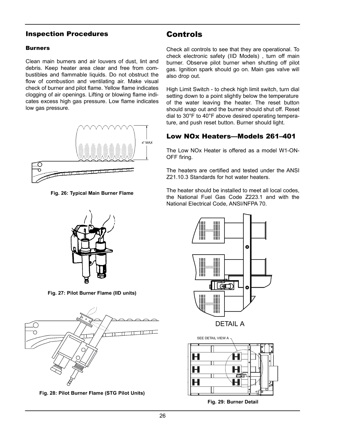
Clean main burners and air louvers of dust, lint and debris. Keep heater area clear and free from com- bustibles and flammable liquids. Do not obstruct the flow of combustion and ventilating air. Make visual check of burner and pilot flame. Yellow flame indicates clogging of air openings. Lifting or blowing flame indi- cates excess high gas pressure. Low flame indicates low gas pressure.
Fig. 26: Typical Main Burner Flame
Fig. 27: Pilot Burner Flame (IID units)
Controls
Check all controls to see that they are operational. To check electronic safety (IID Models) , turn off main burner. Observe pilot burner when shutting off pilot gas. Ignition spark should go on. Main gas valve will also drop out.
High Limit Switch - to check high limit switch, turn dial setting down to a point slightly below the temperature of the water leaving the heater. The reset button should snap out and the burner should shut off. Reset dial to 30°F to 40°F above desired operating tempera- ture, and push reset button. Burner should light.
Low NOx Heaters—Models 261–401
The Low NOx Heater is offered as a model
The heaters are certified and tested under the ANSI Z21.10.3 Standards for hot water heaters.
The heater should be installed to meet all local codes, the National Fuel Gas Code Z223.1 and with the National Electrical Code, ANSI/NFPA 70.
DETAIL A
SEE DETAIL VIEW A
Fig. 28: Pilot Burner Flame (STG Pilot Units)
Fig. 29: Burner Detail
26