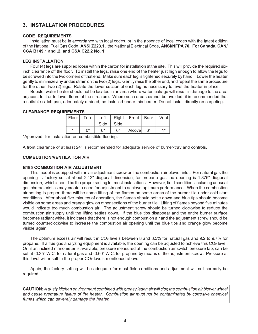
B-195 specifications
The Raypak B-195 is a prominent model in the realm of heating solutions, specifically designed for residential and commercial applications. Known for its robust construction and high efficiency, the B-195 seamlessly combines reliability with advanced technology. This model is particularly favored in the pool and spa industry, as well as for hydronic heating systems.One of the standout features of the Raypak B-195 is its compact design, which allows for easy installation in tight spaces. Despite its smaller footprint, the B-195 does not compromise on performance. It has a btu output of 195,000, making it suitable for both heating large pools and providing adequate heating for homes. The B-195 operates on natural gas, which is both cost-effective and environmentally friendly, promoting greener living solutions.
The unit incorporates a user-friendly digital display and control panel, enabling users to set and adjust temperatures with ease. Its advanced microprocessor control technology ensures accurate temperature regulation and efficient operation. Among the technological highlights is the patented Raypak Cupro-Nickel heat exchanger, which not only enhances the heat transfer efficiency but also extends the lifespan of the unit. This material is highly resistant to corrosion, ensuring durability and reducing maintenance needs.
The B-195 also features an exceptional flow sensing system that automatically adjusts the heater operation based on the water flow rate. This dynamic response ensures optimal performance while preventing overheating, enhancing overall safety. Additionally, the unit comes equipped with a high-efficiency ignition system, allowing for quick starts and consistent heat output.
Another significant aspect of the Raypak B-195 is its compatibility with various automation systems, facilitating smart pool management. This allows users to integrate the heater with their existing pool control systems, enabling remote monitoring and control via smart devices.
In terms of energy efficiency, the B-195 meets and often exceeds industry standards, providing a commendable energy factor. This translates to lower operating costs and reduced environmental impact, making it an ideal choice for energy-conscious consumers.
Overall, the Raypak B-195 stands as a testament to innovation in heating technology, offering a blend of efficiency, reliability, and convenience. Whether for a luxury pool or essential home heating, the B-195 delivers outstanding performance tailored to meet diverse heating needs.

