Wiring a Power Vent Assembly to an Appliance with IID Ignition
WARNING: Disconnect all electrical power to the unit before servicing to avoid potential shock injury or damage to the unit. To change voltages, follow wiring diagram for correct voltage connections. Improper wiring connections can burnout the relay and blower motor.
90 Degree Elbows | 45 Degree Elbows | |||
|
|
|
| |
Quantity | Maximum | Quantity | Maximum | |
Length (ft) | Length (ft) | |||
|
| |||
|
|
|
| |
1 | 30 | 1 | 35 | |
|
|
|
| |
2 | 20 | 2 | 30 | |
|
|
|
| |
3 | 10 | 3 | 25 | |
|
|
|
| |
Table C: Reduced Maximum Equivalent Vent Run
Venting
The vent pipe must be the same size or one size larg- er than what is indicated. The
The
The vent must be installed to prevent the potential accumulation of condensate in the vent pipes. It is rec- ommended that:
a)The vent be installed with a slight downward slope of not more than 1/4” per foot of horizontal run to the vent terminal.
b)The vent be insulated through the length of horizon- tal run.
For appliances installed in extreme cold climate, it is recommended that:
a)The vent be installed with a slight upward slope of not more than 1/4” per foot of horizontal run to the vent terminal. In this case, an approved condensate trap must be installed per applicable codes.
b)The vent be insulated through the length of the hor- izontal run.
4" |
DIAMETER |
LEFT SIDE
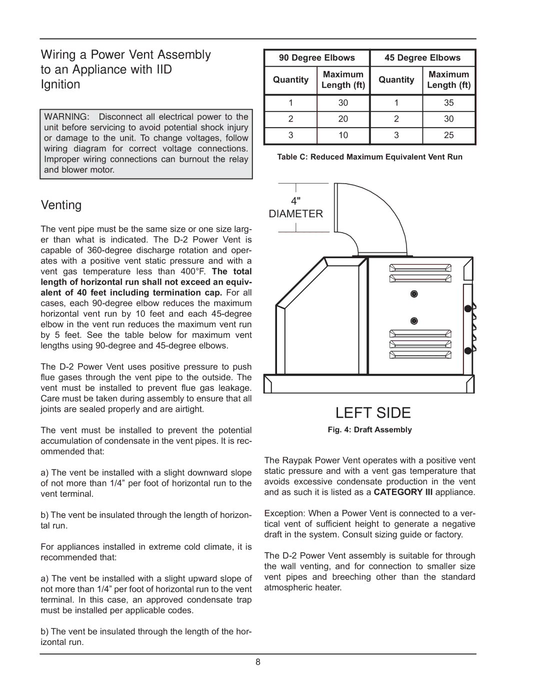
Fig. 4: Draft Assembly
The Raypak Power Vent operates with a positive vent static pressure and with a vent gas temperature that avoids excessive condensate production in the vent and as such it is listed as a CATEGORY III appliance.
Exception: When a Power Vent is connected to a ver- tical vent of sufficient height to generate a negative draft in the system. Consult sizing guide or factory.
The
8
