Manuals
/
Raypak
/
Lawn and Garden
/
Swimming Pool Heater
Raypak
P-1826, P-4001, P-926, P-2100
manual
Gas Supply Connections, Gas Pressure Regulator
Models:
P-2100
P-926
P-4001
P-1826
1
8
36
36
Download
36 pages
20.2 Kb
5
6
7
8
9
10
11
12
Troubleshooting
Specifications
Install
Wiring Diagram-Models
Electrical Wiring
Warranty
Maintenance
Reset time clock
Heat Exchanger Reassembly
Start-Up Procedures
Page 8
Image 8
Page 7
Page 9
Page 8
Image 8
Page 7
Page 9
Contents
Models P-926to P-1826 & P-2100to P-4001
INSTALLATION & OPERATING INSTRUCTIONS
Raytherm Commercial Swimming Pool Heater
Corrosive water voids all warranties
CONTENTS
DANGER
WARNINGS
Pay Attention to These Terms
RECEIVING EQUIPMENT INSTALLATION
GENERAL SPECIFICATIONS
Base Installation
Code Requirements
Clearances
Combustion Air Indoor Units Only
Indoor Heaters
Outdoor Heaters
Vent Piping
Venting Connections
Drafthood Indoor Models
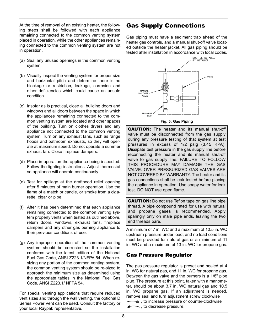
Gas Supply Connections
Gas Pressure Regulator
Venting of Diaphragm Gas Components
Model
1-1/4”
1-1/2”
Water Connections
Flow Switch
CONTROLS
Water Pressure Switch
Automatic Chlorinators and Chemical Feeders
Unitherm Governor Operation
Companion Flange Connections Models
Model No
Connection
Minimum
Model No. Loop* Flow Rates Heater Flow
2.Lace metal strapping or clamps, NOT PROVID- ED through the ¾” slots on the cover and fasten securely to pipe as shown in Fig. 15 & 16. Do not over-tightenclamps
HEATER
Models 0926 thru 1223 with UG
RECOMMENDED FIELD INSTALLED
ISOLATION VALVESFORSERVICE
BLENDEDWATER TEMPERATURE
THERMOMETERATHEATERINLET
Models 2100 thru
HEATEROUTLETTEMPERATURETHERMOMETER
External Auxiliary Bypass Valve Where Required
Auxiliary Bypass Valve Adjustment
926-1223Models Only
Temperature Controls
Electrical Wiring
High & Low Gas Pressure Switches
Low Water Cutoff
Electronic Ignition
Wiring Diagram-Models
Wiring Diagram-Models
Wiring Diagram-Models
Wiring Diagram-Models
Pressure Switch
Pressure Switch Adjustment
SERVICING
General Location Of Controls
START-UP PROCEDURES
Pilot Safety
Two-SpeedPumps
Before Start-Up
Burners
INSPECTION PROCEDURES
After Start-Up
SERVICING PROCEDURES
Tube Cleaning Procedure Typical
Burner Drawer Removal
Gas Valve Removal
Pilot Removal and Cleaning
Heat Exchanger Reassembly
Main Burner and Orifice Removal
Heat Exchanger Removal
Control Well Replacement
Tube Replacement Procedure
Procedure For Cleaning Flue Gas Passageways
Combustion Chamber Removal
MAINTENANCE AND CARE
Unitherm Governor Replacement
UNITHERM GOVERNOR WITH POWER ELEMENT
INLET/OUTLET HEADER OUTLET INLET GASKET
Winterizing Your Heater
IMPORTANT NOTICE
TROUBLESHOOTING
MECHANICAL FOR QUALIFIED SERVICE PERSONNEL ONLY
or refer to heater sizing chart
Reset time clock
Clean filter
Refer to installation instructions
TROUBLESHOOTING HONEYWELL S8600
Intermittent Pilot System
ELECTRICAL ELECTRONIC IGNITION IID IID
START
LIMITED WARRANTY RAYTHERM TYPE P SIZES
HEAT EXCHANGER WARRANTY
ADDITIONAL WARRANTY EXCLUSIONS
PARTS REPLACEMENT
Top
Page
Image
Contents