.
r
nected with reversed polarity. Use fabricated tool (Fig. 28) to
push LED into holder. LED "clicks" into place. Any tool
without a shoulder usually pushes LED out of the holder.
7.Form snipped leadwires as shown in Fig. 31 and connect
new LED pigtails to them. Solder quickly to prevent over-
heating LED.
8.Reconnect black, white and yellow leads from PC board
to complete installation.
TO PC BOARD
BLK .WHT
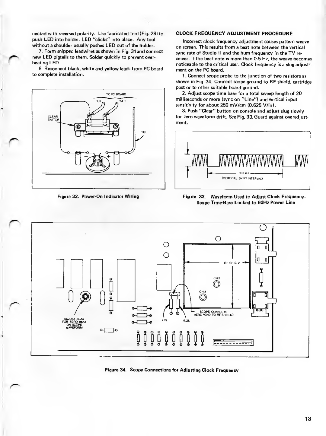
CLOCK FREQUENCY ADJUSTMENT PROCEDURE
Incorrect clock frequency adjustment causes pattern weave
on screen. This results from a beat note between the vertical
sync rate of Studio II and the hum frequency in the TV re-
ceiver. If the beat note is more than 0.5 Hz, the weave becomes
noticeable to the critical user. Clock frequency is a slug adjusts
ment on the PC board.
1Connect scope probe to the junction of two resistors as
shown in Fig. 34. Connect scope ground to RF shield, cartridge
post or to other suitable board ground.
2.Adjust scope time base for a total sweep length of 20
milliseconds or more (sync on "Line") and vertical input
sensitivity for about 250 mV/cm (0.625 V/in).
3.Push "Clear" button on console and adjust slug slowly for zero waveform drift. See Fig. 33. Guard against overadjust-
ment.
r
L,
V1WWVWWWWLW
f
(VERTICAL SYNC INTERVAL)
Figure 32. | Figure 33. Waveform Used to Adjust Clock Frequency. |
| Scope |
r
r
Figure 34. Scope Connections for Adjusting Clock Frequency
r
13