Users Guide
Important Information
Product Registration Product Information
Introduction
Thank you for choosing RCA Scenium
Part 1 DLP- brilliance, in color, design, and technology
Part 2 Why RCA Scenium DLP is better?
Resolution it’s math...that works for you
Format Analog Ntsc HD Digital Atsc
Aspect Ratio
Part 3 Other Key Features of owning an RCA Scenium Hdtv
Digital Signal and Sound
User-friendly Features Help You Personalize Your TV
Integrated Hdtv Tuner with QAM
FireWire with Two-Way DTVLink
What’s Next?
Audio System NetConnect
Record Output Jacks
Table of Contents
Using the TV’s Menu System
Reference
Connections & Setup
Chapter Overview
Connections & Setup
Things to Consider Before You Connect
Choose Your Connection
Components Cables Needed Connection Title Go to
How to Connect TV + VCR + DVD Player
Go to
Viewing the Components
How to Connect TV + Satellite Receiver + VCR
Connect your Satellite Receiver to your TV
Audio Connections
Amplifier
How to Connect TV + Speakers Without A/V Receiver
How to Connect TV + Router via the HDTV’s Ethernet Jack
You should know
How to Connect TV + DTVLink and/or IEEE-1394 Components
You should know
HD Set Top Box
DTVLink Digital Television Link Connectors
Explanation of Input Jacks and Cables
Digital Audio Out Jack and Optical Cable
Ethernet Jack and Cable
Component Video YPbPr Jacks and Cables
Video Jacks and Cables
Composite Audio/Video Jacks and Cables RCA-type
RF Jacks and Coaxial Cables F-type
Back of the TV
Right and Left External Speaker Terminals Used to connect
Internal Speaker Source TV / EXT AMP Switch
TV’s Center Channel Inputs
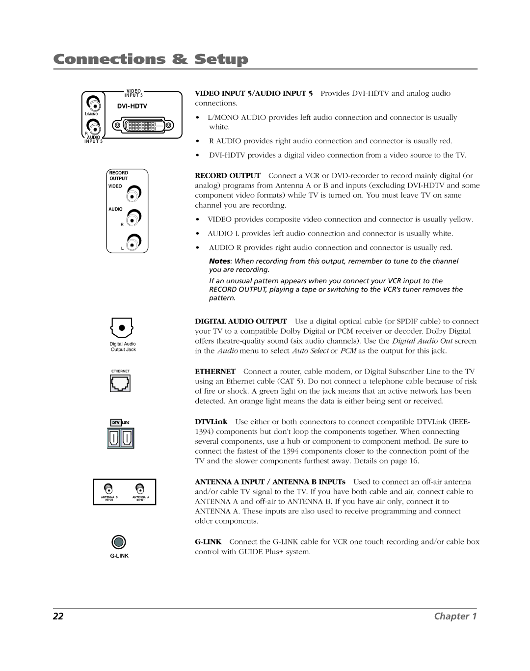
DVI-HDTV
Why You Should Connect the G-LINK Cable
How to Find the Remote Sensor
Placing the G-LINK Wands
Front of Your TV
Button Lighting
Front Input Jacks
Buttons on the Front of the TV
Use the Remote Control to Complete the Assisted Setup
Plug in the TV
Put Batteries in the Remote
Turn on the TV
Complete the Assisted Setup
Guide Plus+ System Setup
Set the Menu Language
Complete Channel Search
Configuring for Cable
Configuring for a VCR
Confirming Your Settings
What to Expect
Next Steps
Changing Channels
Turning the TV On and Off
Using the Remote Control
Overview
Using the Remote Control
Buttons on the Remote Control
Using the Remote Control
Using Direct Entry
Programming the Remote to Operate Other Components
Find Out If You Need to Program the Remote
Programming the Remote
How to Use the Remote After You’ve Programmed It
Using Automatic Code Search
Learning Feature
Adding a Learned Function
Clearing a Learned Function
Deleting ALL Learned Functions
Volume Punchthrough Feature
Deleting ALL Volume Punchthrough Commands
Using the Input Button
Remote Code List
Audio Codes
Cable Box Codes
Cable Box codes cont’d
DVD codes
DVD/VCR Combo Codes
PVR Codes
Using the TV’s Features
Using the TV’s Features
About the Channel Banner
Digital or Analog TV Channels
Mpaa Not Rated
Using the Guide Plus+ System
About the Guide Plus+ System
Guide Plus+ System Menus
Listings
Guide Action Buttons
Expanded Information
Sort
News
Messages
Promotions
Setup
Schedule
Channels
Promotions and Advertising
Parental Controls
Lock/Unlock TV
How V-Chip Works for the USA and Canada
USA V-Chip TV Ratings
Editing Channels in the Channel Lists
USA V-Chip Rating Limit Screen
TV-14
Blocking Specific Content Themes
Blocking Age-Based Ratings
Viewing Age-Based Ratings
Hierarchy of Age-Based Ratings
Viewing Specific Content Themes
Chip Movie Rating Limit
Blocking Movie Ratings
Viewing Movie Ratings
Canada V-Chip
Age-Based Canada V-Chip English Rating System
18+
14+
Age-Based Canada V-Chip French Rating System 18+
16+
13+
Canada V-Chip
Auto Tuning Feature
DSL unit. If you want access to the web browser to require
When a button listed below is pressed on the remote control
Front Button Block
PIP Picture-in-Picture Operation
PIP Buttons
Using the PIP Feature
PIP Problems?
Using the Web Browser
Browser Times Out Automatically
Saving Your Favorite URLs
Recording
Controlling the Web Browser
Web Browser Button Interaction
Remote Front Panel Browser Function
Set up 1394 Recording Preferences
Mpaa Not Rated Normal 1080i HD 00h00m00s of 00h00m00s
Using the TV’s Menu System
Using the TV’s Menu System
Menus, On-screen Help, and Control Panels
Sliders
Check Boxes
Picture Settings
Picture Presets
Picture Quality Menu
Advanced Settings
Auto Color
Color Warmth
Noise Reduction
Go Back Edge Enhancement
Go Back Edge Enhancement Green Stretch
Go Back Edge Enhancement Green Stretch Contrast Expand
Reset Controls
Equalizer Presets
Audio Menu
Audio Processor
Sound Logic
Audio Language
SAP Second Audio Program
Balance
Fixed/Variable Out
Digital Audio Out
Time Menu
Connections Menu
Antenna Info
Software Upgrade
Signal Source
Signal Type
Channel Search
Auto Tuning
Setup DTVLink
Special Features
Ethernet Setup
Preferences Menu
Closed Captioning
Screen Format
Go Back Caption Display Analog Captions
Go Back Caption Display Analog Captions Digital Captions
Caption Style Main Menu Preferences Closed Captioning
Record Output
Color Scheme
Translucency
Lamp Power
Lamp Power Main Menu Preferences
Digital Channel Info Lamp Power
Menu Language
Reference
Troubleshooting
References
Blank screen
Unusual sound quality
Humming or buzzing noise
No picture, sound okay
No picture, no sound but TV is on
Sound okay, picture poor
Black box appears on the screen
Every time I turn on the TV, the Guide is on the screen
Don’t remember my password and I want to unlock the TV
Doesn’t tune to correct antenna input
Rating limits don’t work
Hdtv Specifications
Convenience
Accessory Information
Replacement Lamp
Accessory Order Form
DV6
Video Accessories PO Box Ronks, PA
Placing an Order
Limited Warranty
Limitation of Warranty
How State Law relates to warranty
Product Registration
If you purchased your unit outside the United States
FCC Information
Symbols
Index
External Speakers Output 13
Video Input 3
Page
Thomson Inc
North Meridian Street Indianapolis,
Tocom 1614682B