5 specifications
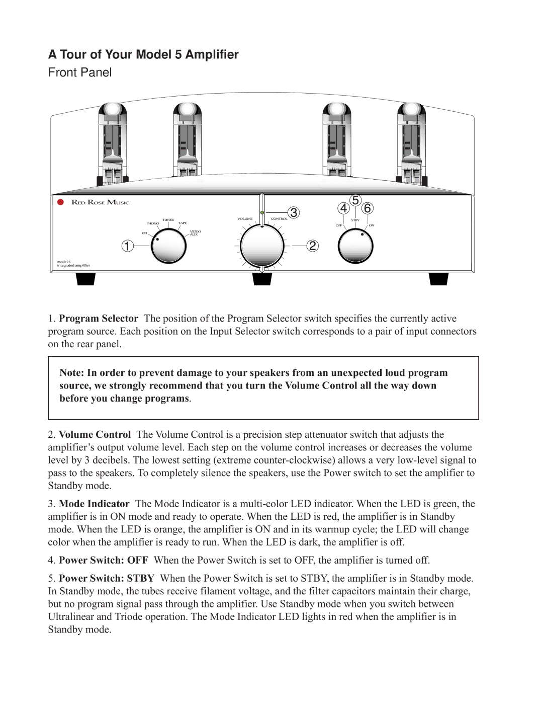
Red Rose Music 5 is a groundbreaking advancement in the realm of audio technologies, revolutionizing the way we experience sound. Renowned for its rich, immersive sound quality, this state-of-the-art music system is designed for audiophiles and casual listeners alike. Its primary purpose is to provide unparalleled clarity and depth, ensuring that every note and nuance is heard as the artist intended.One of the main features of Red Rose Music 5 is its advanced digital processing capabilities. It utilizes sophisticated algorithms to enhance sound quality, providing listeners with an authentic audio experience. These algorithms analyze incoming audio signals and optimize them in real-time, resulting in a listening experience that captures the essence of live performances.
The system also incorporates high-resolution audio formats, allowing users to enjoy music in stunning detail. Supporting formats like FLAC and DSD, Red Rose Music 5 caters to users who prioritize quality over convenience, ensuring that even the most intricate compositions are rendered beautifully. This feature is complemented by an impressive dynamic range, which allows for a stark contrast between soft and loud sounds, providing a fuller listening experience.
Another noteworthy characteristic is the connectivity options available with Red Rose Music 5. With support for Bluetooth, Wi-Fi, and various digital inputs, users can easily stream music from their smartphones, tablets, or computers. This flexibility makes it possible to enjoy an expansive library of music without the clutter of physical media.
The user interface of Red Rose Music 5 is designed for simplicity and ease of use. Featuring a responsive touch-screen display, navigating through playlists and settings is intuitive. Customization options allow users to tailor their listening experience according to personal preferences, ensuring that every session is unique.
Design-wise, Red Rose Music 5 embodies elegance. Its sleek, modern aesthetic, combined with high-quality materials, makes it a beautiful addition to any home. The system is engineered not only for performance but also for longevity, incorporating components that can withstand the rigors of regular use.
In essence, Red Rose Music 5 is a versatile and sophisticated music system that caters to the needs of modern audiophiles. With its superior sound quality, wide range of connectivity options, and user-friendly interface, it stands as a testament to technological advancement in the world of audio, delivering an extraordinary listening experience.

