Manuals
/
RedMax
/
Lawn and Garden
/
Trimmer
RedMax
EXZ2500S-BC
manual
EX-LRT S/N 000531 and up, 54
Models:
EXZ2500S-BC
1
54
64
64
Download
64 pages
10.86 Kb
51
52
53
54
55
56
57
58
Troubleshooting
Specification
Install
Parts list
Maintenance Chart
Symbols on the machine
Warranty
Maintenance
Set up
Adjusting Throttle Cable
Page 54
Image 54
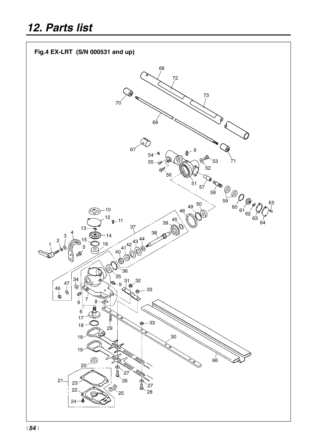
12. Parts list
Fig.4
EX-LRT
(S/N 000531 and up)
54
Page 53
Page 55
Page 54
Image 54
Page 53
Page 55
Contents
OWNER/OPERATOR Manual
T3087-93110
Page
Safety First
Contents
Parts location
4
EX-LRT
Specifications
EX-BC
EX-PS
6
Symbols on the machine
Type de moteur 1KZXS.0254QR EM Cylindrée du moteur 25,4cc
7
Working Circumstance
For safe operation
Working Condition
8
Working Plan
9
Before Starting the Engine
Starting the Engine
10
Using the Product
11
Handling Fuel
Maintenance
If Someone Comes
12
Transportation
13
Set up
Debris guard Plate Screw
EX-BC SE1 SE2 Installing Debris Guard
Installing Cutting Head SE2
EX-BC SE3 Balance Unit
EX-LRT SE1 Attaching the Trimming Mechanism SE1
Main pipe Trimming mechanism Screw hole Fastening bolt
16
EX-PS SE3
EX-PS SE1 Attaching the Pruning Mechanism SE1
EX-PS SE2
17
Hole Moving direction Chain tensioner nut
Chain tension adjusting screw Loosen Tighten
EX-PS SE4 EX-PS SE5 EX-PS SE6
18
Bracket
EX-HE SE1 EX-HE SE2 EX-HE SE3 EX-HE SE4
Clamp bolt Lock screw
19
Recommended Mixing Ratio Gasoline 50OIL
HOW to MIX Fuel
Fuel
20
Fueling the Unit
For Your Engine LIFE, Avoid
21
Operation
22
OP6 OP7 OP8
Stopping Engine OP6
23
OP9
Adjusting Throttle Cable
Adjusting Idling Speed OP10
24
Trimming Grass and Weeds
Adjusting the Line Length
EX-BC OP1 Cutting Work Line Head Usage
25
26
Cutting Method
EX-BC OP4 EX-BC OP5 EX-BC OP6
Bracket Handle
27
Operation
EX-BC OP7 EX-BC OP8
28
Controlling Blade Bounce
How you can reduce the chance of kick out
How you can maintain the best control
29
EX-BC OP9 Maintenance Blade
Transporting the Unit
30
EX-LRT OP1
Adjusting the Angle of the Cutting Blades OP1
Operation EX-LRT only
Clamp lever Trimming mechanism
EX-PS OP1 EX-PS OP2 Checking OIL Supply
Adjusting OIL Flow Rate
Operation EX-PS only
32
33
Operation EX-HE only
EX-HE OP1
34
Maintenance
Maintenance Chart
35
36
Spark arrester
MA4 Muffler
Spark Arrester
Intake AIR Cooling Vent
MA6
Procedures to be Performed After Every 100 Hours of USE
MA51
Cylinder Intake air cooling vent back
Gear Case MA5
Maintenance EX-BC only
For safety reasons, do not use metalreinforced line
39
Blades MA1
EX-LRT MA1 EX-LRT MA2
40
Quick TIP
Guide BAR
Maintenance EX-PS only
EX-PS MA1 MA2 MA3 Oiling Port
41
Sprocket
EX-PS MA4 MA5 MA6
42
SAW Chain
EX-PS MA7 MA8 MA9
43
Maintenance EX-HE only
MA1 Gear Case
44
Storage
45
Troubleshooting guide
Check Probable Causes Action
46
Parts list
EX-LRT ATT EX-PS ATT EX-HE ATT
EXZ-PU S/N 302845 and up
48
49
EX-BC S/N 302960 and up
50
51
Engine Unit 352001 and up
52
53
Description Part Number Qty
EX-LRT S/N 000531 and up
54
55
Casing B
EX-PS S/N 000000 and up
56
57
EX-HE S/N 000101 and up
58
59
Manufacturer’s warranty coverage
RedMax 2-YEAR Limited Warranty
RedMax Garantie limitée à 2 ans
Page
Komatsu Zenoah America INC
Top
Page
Image
Contents