520M/520TS specifications
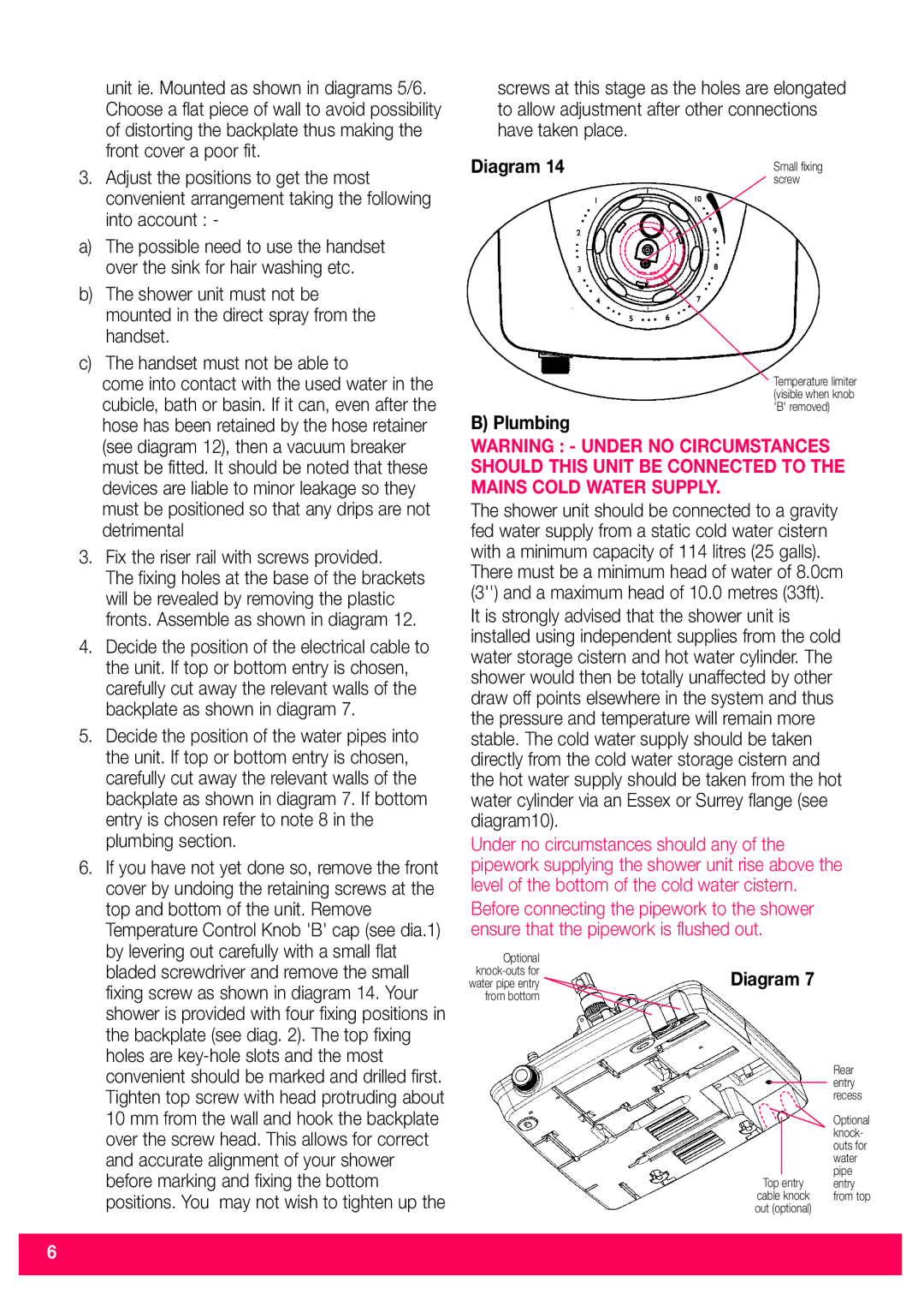
The Redring 520M and 520TS are highly regarded electric water heaters designed for convenience and efficiency in domestic and light commercial applications. Both models exemplify Redring's commitment to delivering innovative heating solutions suitable for various hot water needs.One of the standout features of the Redring 520M and 520TS is their compact size, making them an ideal choice for installations in limited spaces such as kitchens, bathrooms, or utility rooms. Their sleek design allows them to blend seamlessly into any decor, enhancing aesthetics while providing functionality.
These models are equipped with advanced heating technologies that ensure rapid and consistent water heating. The Redring 520M offers a powerful 2kW heating element, while the 520TS features a slightly higher 3kW option, suitable for environments requiring higher hot water demands. Shoppers can choose between these specifications based on their specific needs.
Both models come with user-friendly controls that allow users to adjust temperature settings with ease. The Redring 520M features a simple dial control, while the 520TS is enhanced with digital controls for more precise temperature management. This versatility ensures users can tailor their hot water experience and adapt to various situations.
Safety is paramount in the design of the Redring 520M and 520TS. They are equipped with overheat protection systems that automatically shut off the unit if the water temperature exceeds a predetermined limit, thus minimizing the risk of scalding. Additionally, an integrated pressure relief valve provides extra safety, ensuring that the unit operates within safe pressure levels.
Energy efficiency is another critical characteristic of both models. The near-instantaneous heating capabilities reduce waiting times and minimize energy wastage compared to traditional water heating systems. Furthermore, the likelihood of water standing idle in a hot water tank is eliminated, leading to significant cost savings over time.
In summary, the Redring 520M and 520TS offer efficient, safe, and reliable hot water solutions. Their compact design, advanced heating technologies, and emphasis on user-friendliness make them perfect additions to any home or small business. With Redring's reputation for quality and innovative engineering, these models serve both functionality and convenience for various hot water needs. The Redring 520M and 520TS stand as exemplary products in modern electric water heating solutions, combining quality, energy efficiency, and ease of use for today's consumers.

