Mounting the Powerstar
WARNING:
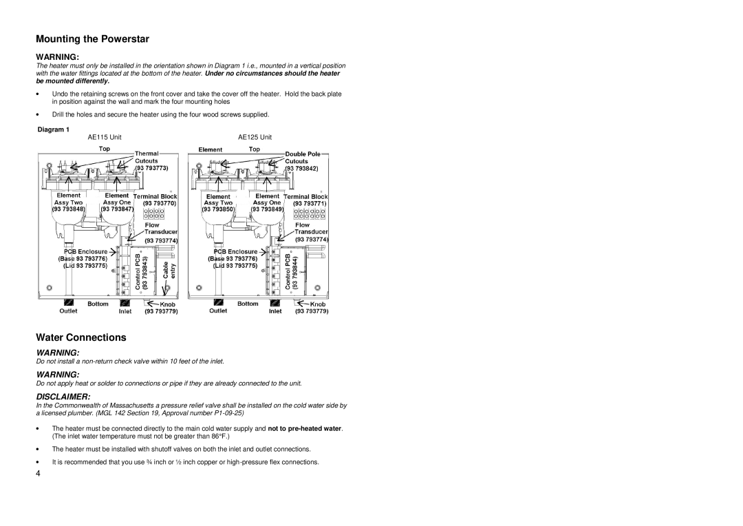
The heater must only be installed in the orientation shown in Diagram 1 i.e., mounted in a vertical position with the water fittings located at the bottom of the heater. Under no circumstances should the heater be mounted differently.
∙Undo the retaining screws on the front cover and take the cover off the heater. Hold the back plate in position against the wall and mark the four mounting holes
∙Drill the holes and secure the heater using the four wood screws supplied.
Diagram 1
AE115 Unit | AE125 Unit |
Water Connections
WARNING:
Do not install a
WARNING:
Do not apply heat or solder to connections or pipe if they are already connected to the unit.
DISCLAIMER:
In the Commonwealth of Massachusetts a pressure relief valve shall be installed on the cold water side by a licensed plumber. (MGL 142 Section 19, Approval number
∙The heater must be connected directly to the main cold water supply and not to
∙The heater must be installed with shutoff valves on both the inlet and outlet connections.
∙It is recommended that you use ¾ inch or ½ inch copper or
4