Canada wiring – auxiliary terminal block and connections
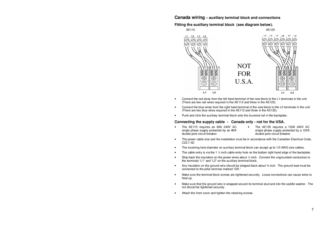
Fitting the auxiliary terminal block (see diagram below).
AE115 | AE125 |
NOT
FOR
U.S.A.
∙Connect the red wires from the left hand terminal of the new block to the L1 terminals in the unit. (There are two red wires required in the AE115 and three in the AE125).
∙Connect the blue wires from the right hand terminal of the new block to the L2 terminals in the unit. (There are two blue wires required in the AE115 and three in the AE125).
∙Push and click the auxiliary terminal block onto the louvered rail in the backplate.
Connecting the supply cable - Canada only - not for the USA.
∙ | The AE115 requires an 80A 240V AC | ∙ | The AE125 requires a 120A 240V AC |
| single phase supply protected by an 80A |
| single phase supply protected by a 120A |
| double pole circuit breaker. |
| double pole circuit breaker. |
∙The power cable size and the installation must be in accordance with the Canadian Electrical Code,
∙The incoming hole diameter on auxiliary terminal block can accept up to 1/0 AWG size cables.
∙The cable entry is via the 1 ¼ inch cable entry hole on the bottom right hand edge of the backplate.
∙Strip back the insulation on the power wires about ½ inch. Connect the ungrounded conductors to the terminals “L1” and “L2” on the auxiliary terminal block.
∙Any insulation on the ground wire should be stripped back about ¾ inch. The ground lead must be connected to the pillar terminal marked “GR.”
∙Make sure the terminal block screws are tightened securely. Loose connections can cause wires to heat up.
∙Make sure that the ground wire is wrapped around its terminal stud and into the saddle washer. The nut should be tightened securely.
∙Attach the front cover and tighten the retaining screws.
7