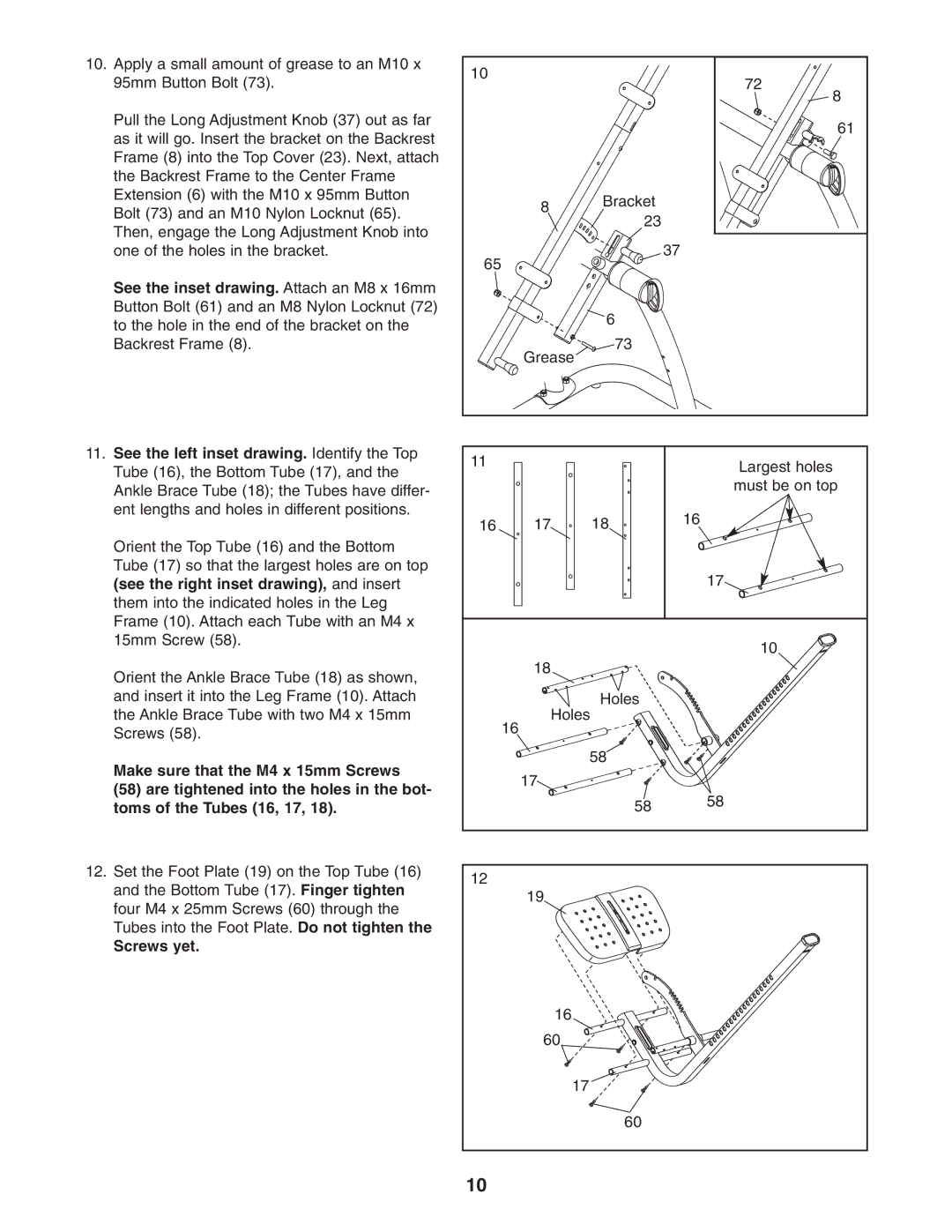
10.Apply a small amount of grease to an M10 x 95mm Button Bolt (73).
Pull the Long Adjustment Knob (37) out as far as it will go. Insert the bracket on the Backrest Frame (8) into the Top Cover (23). Next, attach the Backrest Frame to the Center Frame Extension (6) with the M10 x 95mm Button Bolt (73) and an M10 Nylon Locknut (65). Then, engage the Long Adjustment Knob into one of the holes in the bracket.
See the inset drawing. Attach an M8 x 16mm Button Bolt (61) and an M8 Nylon Locknut (72) to the hole in the end of the bracket on the Backrest Frame (8).
10 | 72 | |
| ||
| 8 | |
| 61 | |
8 | Bracket | |
23 | ||
| ||
65 | 37 | |
| ||
| 6 | |
Grease | 73 | |
|
11.See the left inset drawing. Identify the Top Tube (16), the Bottom Tube (17), and the Ankle Brace Tube (18); the Tubes have differ- ent lengths and holes in different positions.
Orient the Top Tube (16) and the Bottom Tube (17) so that the largest holes are on top (see the right inset drawing), and insert them into the indicated holes in the Leg Frame (10). Attach each Tube with an M4 x 15mm Screw (58).
Orient the Ankle Brace Tube (18) as shown, and insert it into the Leg Frame (10). Attach the Ankle Brace Tube with two M4 x 15mm Screws (58).
Make sure that the M4 x 15mm Screws
(58) are tightened into the holes in the bot- toms of the Tubes (16, 17, 18).
12.Set the Foot Plate (19) on the Top Tube (16) and the Bottom Tube (17). Finger tighten four M4 x 25mm Screws (60) through the Tubes into the Foot Plate. Do not tighten the
Screws yet.
11 | Largest holes |
| |
| must be on top |
16 | 17 | 18 | 16 |
| |||
|
|
| 17 |
|
|
| 10 |
| 18 |
|
|
|
| Holes |
|
| Holes |
| |
| 16 |
|
|
|
| 58 |
|
| 17 |
|
|
|
| 58 | 58 |
|
|
| |
12 |
|
|
|
| 19 |
|
|
| 16 |
|
|
| 60 |
|
|
|
| 17 |
|
|
| 60 |
|
10 |
|
|
|