EL-3 specifications
The Remington Power Tools EL-3 is a standout in the world of electric chainsaws, bringing power and efficiency to both professional landscapers and DIY enthusiasts. Known for its robust performance and user-friendly design, the EL-3 has quickly gained a reputation as a reliable tool for tackling various cutting tasks.One of the main features of the EL-3 is its powerful motor, which delivers an impressive level of torque and cutting speed. This motor ensures that the chainsaw can easily handle thick branches and logs without stalling. The combination of power and efficiency makes the EL-3 ideal for both heavy-duty work and lighter landscaping tasks.
The EL-3 boasts an ergonomic design, featuring an adjustable handle that allows users to find the perfect grip and angle for maximum comfort during use. This consideration for user experience is complemented by the lightweight nature of the tool, which reduces fatigue during extended periods of operation. The well-balanced design ensures that users can maneuver the chainsaw effortlessly, even in tight spaces.
Another significant feature of the Remington EL-3 is its automatic oiling system. This technology ensures that the chain remains lubricated, extending its life and improving cutting performance. The oil reservoir is transparent, allowing users to easily monitor the oil levels and refill as necessary without any guesswork.
Safety is paramount in any power tool, and the EL-3 incorporates several safety features to protect users. It comes equipped with a chain brake that quickly stops the chain's movement in case of kickback, reducing the risk of accidents. Additionally, the tool is designed with a low kickback chain, which further enhances safety during operation.
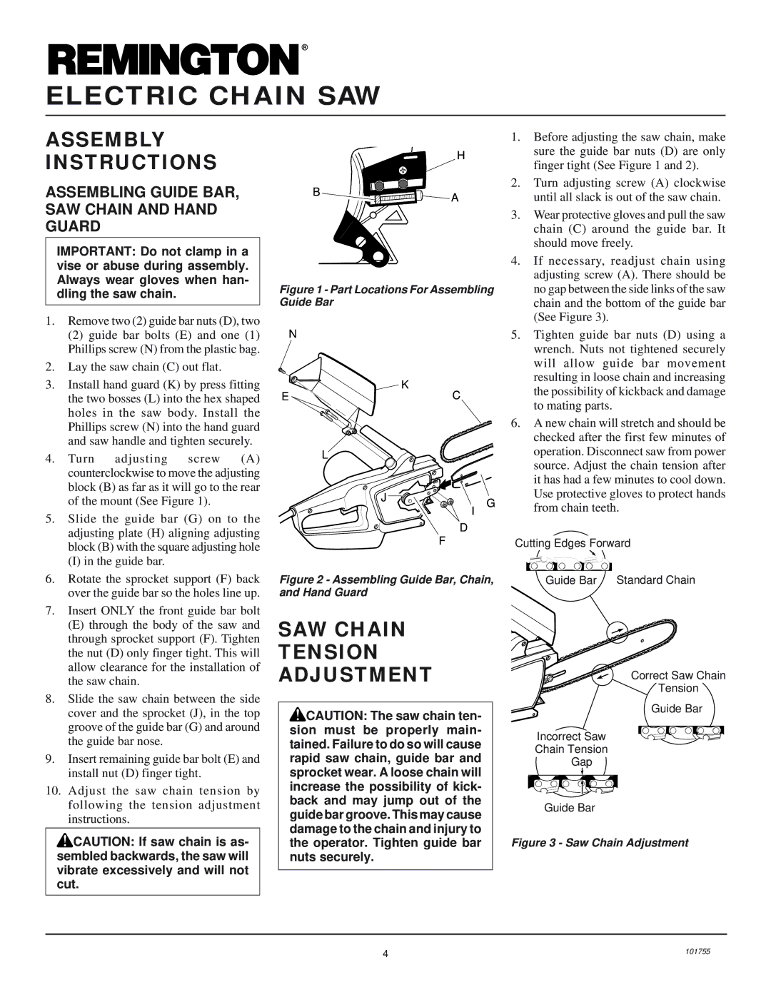
The EL-3 is also designed for easy maintenance. The tool-less chain tensioning feature allows users to adjust the chain tension without needing additional tools, making it straightforward to keep the saw in optimal condition. This feature is particularly appreciated by both homeowners and professionals who value efficiency.
In summary, the Remington Power Tools EL-3 excels in performance, comfort, and safety. With its powerful motor, ergonomic design, automatic oiling system, and user-friendly maintenance features, it stands out as a reliable choice for anyone in need of a high-quality electric chainsaw. Whether for trimming trees, clearing brush, or cutting firewood, the EL-3 delivers consistent results that make it a must-have for both casual users and dedicated professionals.

