5.BOARD OPTIONS
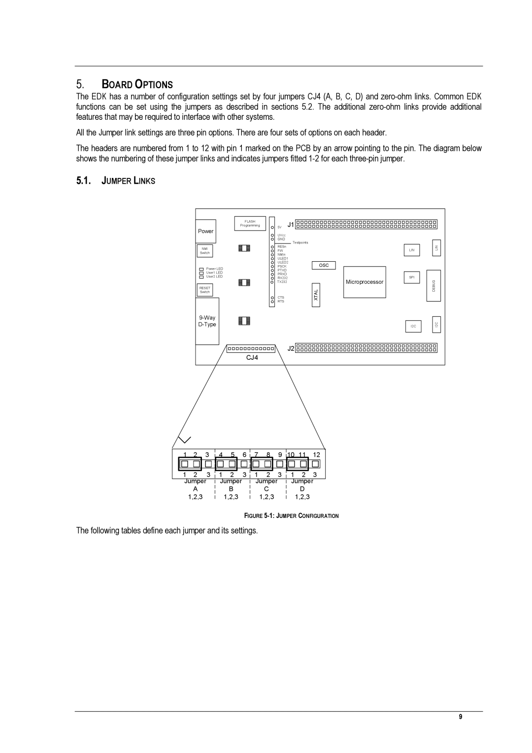
The EDK has a number of configuration settings set by four jumpers CJ4 (A, B, C, D) and
All the Jumper link settings are three pin options. There are four sets of options on each header.
The headers are numbered from 1 to 12 with pin 1 marked on the PCB by an arrow pointing to the pin. The diagram below shows the numbering of these jumper links and indicates jumpers fitted
5.1.JUMPER LINKS
Power
NMI
Switch
Power LED
User1 LED
User2 LED
RESET
Switch
FLASH |
| J1 |
|
Programming | 5V |
| |
| UVcc |
|
|
| GND | Testpoints |
|
| RESn |
| |
|
| LIN | |
| FW |
| |
| NMIn |
|
|
| ULED1 |
| |
| ULED2 | OSC | |
| PSCK |
| |
| PTXD |
|
|
| PRXD |
| SPI |
| RX232 | ||
| TX232 |
| Microprocessor |
| CTS |
| XTAL |
| RTS |
| |
|
|
| |
|
|
| I2C |
|
| J2 |
|
CJ4 |
|
|
|
LIN
DEBUG
I2C
| 1 | 2 | 3 |
| 4 | 5 |
| 6 |
|
| 7 | 8 |
| 9 |
| 10 11 | 12 |
| |
|
|
|
|
|
|
|
|
|
|
|
|
|
|
|
|
|
|
|
|
|
|
| 3 |
|
|
|
| 3 |
|
|
|
|
| 3 |
|
|
| 3 |
|
| 1 | 2 |
| 1 | 2 |
|
|
| 1 | 2 |
|
| 1 | 2 |
| ||||
|
|
|
| ||||||||||||||||
| Jumper |
| Jumper |
|
|
| Jumper |
|
| Jumper | |||||||||
|
|
|
|
|
| ||||||||||||||
|
| A |
|
|
| B |
|
|
|
| C |
|
|
| D |
|
| ||
|
|
|
|
|
|
|
|
|
|
|
|
|
| ||||||
|
| 1,2,3 |
|
|
| 1,2,3 |
|
|
|
| 1,2,3 |
|
|
| 1,2,3 |
|
| ||
|
|
|
|
|
|
|
|
|
|
|
|
|
| ||||||
|
|
|
|
|
|
|
|
|
|
|
|
|
| ||||||
FIGURE 5-1: JUMPER CONFIGURATION
The following tables define each jumper and its settings.
9