5.3.3.SPI – SERIAL PERIPHERAL INTERFACE
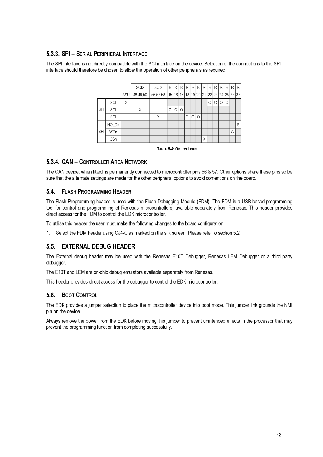
The SPI interface is not directly compatible with the SCI interface on the device. Selection of the connections to the SPI interface should therefore be chosen to allow the operation of other peripherals as required.
|
|
| SCI2 | SCI2 | R | R | R | R | R | R | R | R | R | R | R | R | R |
|
|
|
|
|
|
|
|
|
|
|
|
|
|
|
|
|
|
|
| SSU | 48,49,50 | 56,57,58 | 15 | 16 | 17 | 18 | 19 | 20 | 21 | 22 | 23 | 24 | 25 | 35 | 37 |
|
|
|
|
|
|
|
|
|
|
|
|
|
|
|
|
|
|
SPI | SCI | X |
|
|
|
|
|
|
|
|
| O | O | O | O |
|
|
SCI |
| X |
| O | O | O |
|
|
|
|
|
|
|
|
|
| |
| SCI |
|
| X |
|
|
| O | O | O |
|
|
|
|
|
|
|
SPI | HOLDn |
|
|
|
|
|
|
|
|
|
|
|
|
|
|
| S |
WPn |
|
|
|
|
|
|
|
|
|
|
|
|
|
| S |
| |
| CSn |
|
|
|
|
|
|
|
|
| X |
|
|
|
|
|
|
|
|
|
|
|
|
|
|
|
|
|
|
|
|
|
|
|
|
TABLE
5.3.4.CAN – CONTROLLER AREA NETWORK
The CAN device, when fitted, is permanently connected to microcontroller pins 56 & 57. Other options share these pins so be sure that the alternate settings are made for the other peripheral options to avoid contentions on the board.
5.4.FLASH PROGRAMMING HEADER
The Flash Programming header is used with the Flash Debugging Module (FDM). The FDM is a USB based programming tool for control and programming of Renesas microcontrollers, available separately from Renesas. This header provides direct access for the FDM to control the EDK microcontroller.
To utilise this header the user must make the following changes to the board configuration.
1.Select the FDM header using
5.5. EXTERNAL DEBUG HEADER
The External debug header may be used with the Renesas E10T Debugger, Renesas LEM Debugger or a third party debugger.
The E10T and LEM are
5.6.BOOT CONTROL
The EDK provides a jumper selection to place the microcontroller device into boot mode. This jumper link grounds the NMI pin on the device.
Always remove the power from the EDK before moving this jumper to prevent unintended effects in the processor that may prevent the programming function from completing successfully.
12