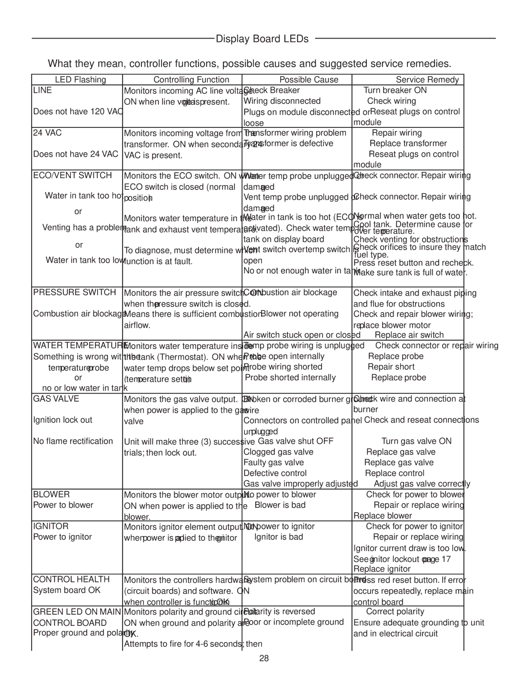
Display Board LEDs
What they mean, controller functions, possible causes and suggested service remedies.
LED Flashing | Controlling Function | Possible Cause | Service Remedy | |
LINE | Monitors incoming AC line voltage. | Check Breaker | Turn breaker ON | |
| ON when line voltage is present. | Wiring disconnected | Check wiring | |
Does not have 120 VAC |
| Plugs on module disconnected or | Reseat plugs on control | |
|
| loose | module | |
24 VAC | Monitors incoming voltage from the | Transformer wiring problem | Repair wiring | |
| transformer. ON when secondary 24 | Transformer is defective | Replace transformer | |
Does not have 24 VAC | VAC is present. |
| Reseat plugs on control | |
|
|
| module | |
ECO/VENT SWITCH | Monitors the ECO switch. ON when | Water temp probe unplugged or | Check connector. Repair wiring | |
Water in tank too hot | ECO switch is closed (normal | damaged | Check connector. Repair wiring | |
position). | Vent temp probe unplugged or | |||
or |
| damaged | Normal when water gets too hot. | |
Monitors water temperature in the | Water in tank is too hot (ECO is | |||
| ||||
Venting has a problem | tank and exhaust vent temperature. | activated). Check water temp in | Cool tank. Determine cause for | |
over temperature. | ||||
or |
| tank on display board | Check venting for obstructions | |
To diagnose, must determine which | Vent switch overtemp switch is | Check orifices to insure they match | ||
| ||||
Water in tank too low | function is at fault. | open | fuel type. | |
Press reset button and recheck. | ||||
|
| No or not enough water in tank. | Make sure tank is full of water. | |
|
|
|
| |
PRESSURE SWITCH | Monitors the air pressure switch. ON | Combustion air blockage | Check intake and exhaust piping | |
Combustion air blockage | when the pressure switch is closed. | Blower not operating | and flue for obstructions | |
Means there is sufficient combustion | Check and repair blower wiring; | |||
| airflow. |
| replace blower motor | |
|
| Air switch stuck open or closed | Replace air switch | |
WATER TEMPERATURE | Monitors water temperature inside | Temp probe wiring is unplugged | Check connector or repair wiring | |
Something is wrong with the | the tank (Thermostat). ON when the | Probe open internally | Replace probe | |
temperature probe | water temp drops below set point | Probe wiring shorted | Repair short | |
or | (temperature setting). | Probe shorted internally | Replace probe | |
no or low water in tank |
|
|
| |
GAS VALVE | Monitors the gas valve output. ON | Broken or corroded burner ground | Check wire and connection at | |
| when power is applied to the gas | wire | burner | |
Ignition lock out | valve | Connectors on controlled panel | Check and reseat connections | |
|
| unplugged |
| |
No flame rectification | Unit will make three (3) successive | Gas valve shut OFF | Turn gas valve ON | |
| trials; then lock out. | Clogged gas valve | Replace gas valve | |
|
| Faulty gas valve | Replace gas valve | |
|
| Defective control | Replace control | |
|
| Gas valve improperly adjusted | Adjust gas valve correctly | |
BLOWER | Monitors the blower motor output. | No power to blower | Check for power to blower | |
Power to blower | ON when power is applied to the | Blower is bad | Repair or replace wiring | |
| blower. |
| Replace blower | |
IGNITOR | Monitors ignitor element output. ON | No power to ignitor | Check for power to ignitor | |
Power to ignitor | when power is applied to the ignitor | Ignitor is bad | Repair or replace wiring | |
|
|
| Ignitor current draw is too low. | |
|
|
| See ignitor lockout on page 17 | |
|
|
| Replace ignitor | |
CONTROL HEALTH | Monitors the controllers hardware | System problem on circuit board | Press red reset button. If error | |
System board OK | (circuit boards) and software. ON |
| occurs repeatedly, replace main | |
| when controller is functioning OK |
| control board | |
GREEN LED ON MAIN | Monitors polarity and ground circuit. | Polarity is reversed | Correct polarity | |
CONTROL BOARD | ON when ground and polarity are | Poor or incomplete ground | Ensure adequate grounding to unit | |
Proper ground and polarity | OK. |
| and in electrical circuit | |
| Attempts to fire for |
|
| |
|
|
|
|
28