Induced Draft Gas continued.

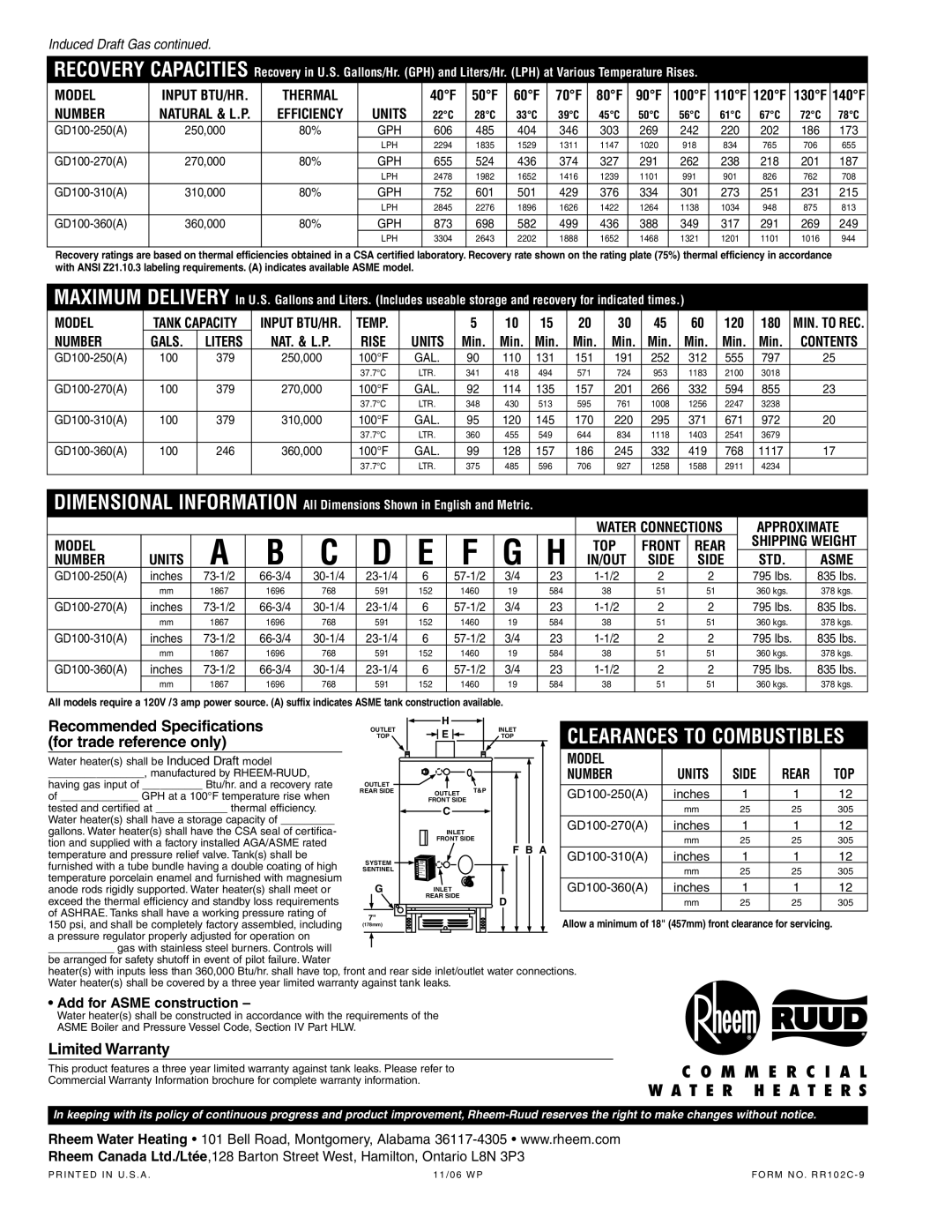
RECOVERY CAPACITIES Recovery in U.S. Gallons/Hr. (GPH) and Liters/Hr. (LPH) at Various Temperature Rises.

MODEL

INPUT BTU/HR.

THERMAL


40°F

50°F

60°F

70°F

80°F

90°F

100°F

110°F

120°F

130°F

140°F

NUMBER

NATURAL & L.P.

EFFICIENCY

UNITS

22°C

28°C

33°C

39°C

45°C

50°C

56°C

61°C

67°C

72°C

78°C

GD100-250(A)

250,000

80%

GPH

606

485

404

346

303

269

242

220

202

186

173


LPH

2294

1835

1529

1311

1147

1020

918

834

765

706

655

GD100-270(A)

270,000

80%

GPH

655

524

436

374

327

291

262

238

218

201

187


LPH

2478

1982

1652

1416

1239

1101

991

901

826

762

708

GD100-310(A)

310,000

80%

GPH

752

601

501

429

376

334

301

273

251

231

215


LPH

2845

2276

1896

1626

1422

1264

1138

1034

948

875

813


GD100-360(A)

360,000

80%

GPH

873

698

582

499

436

388

349

317

291

269

249


LPH

3304

2643

2202

1888

1652

1468

1321

1201

1101

1016

944


Recovery ratings are based on thermal efficiencies obtained in a CSA certified laboratory. Recovery rate shown on the rating plate (75%) thermal efficiency in accordance with ANSI Z21.10.3 labeling requirements. (A) indicates available ASME model.

MAXIMUM DELIVERY In U.S. Gallons and Liters. (Includes useable storage and recovery for indicated times.)

MODEL

TANK CAPACITY

INPUT BTU/HR.

TEMP.


5

10

15

20

30

45

60

120

180

MIN. TO REC.

NUMBER

GALS.

LITERS

NAT. & L.P.

RISE

UNITS

Min.

Min.

Min.

Min.

Min.

Min.

Min.

Min.

Min.

CONTENTS

GD100-250(A)

100

379

250,000

100°F

GAL.

90

110

131

151

191

252

312

555

797

25


37.7°C

LTR.

341

418

494

571

724

953

1183

2100

3018


GD100-270(A)

100

379

270,000

100°F

GAL.

92

114

135

157

201

266

332

594

855

23


37.7°C

LTR.

348

430

513

595

761

1008

1256

2247

3238


GD100-310(A)

100

379

310,000

100°F

GAL.

95

120

145

170

220

295

371

671

972

20


37.7°C

LTR.

360

455

549

644

834

1118

1403

2541

3679


GD100-360(A)

100

246

360,000

100°F

GAL.

99

128

157

186

245

332

419

768

1117

17


37.7°C

LTR.

375

485

596

706

927

1258

1588

2911

4234


DIMENSIONAL INFORMATION All Dimensions Shown in English and Metric.


WATER CONNECTIONS

APPROXIMATE

MODEL


A

B

C

D

E

F

G

H

TOP

FRONT

REAR

SHIPPING

WEIGHT

NUMBER

UNITS

IN/OUT

SIDE

SIDE

STD.

ASME

GD100-250(A)

inches

73-1/2

66-3/4

30-1/4

23-1/4

6

57-1/2

3/4

23

1-1/2

2

2

795 lbs.

835 lbs.


mm

1867

1696

768

591

152

1460

19

584

38

51

51

360 kgs.

378 kgs.


GD100-270(A)

inches

73-1/2

66-3/4

30-1/4

23-1/4

6

57-1/2

3/4

23

1-1/2

2

2

795 lbs.

835 lbs.


mm

1867

1696

768

591

152

1460

19

584

38

51

51

360 kgs.

378 kgs.

GD100-310(A)

inches

73-1/2

66-3/4

30-1/4

23-1/4

6

57-1/2

3/4

23

1-1/2

2

2

795 lbs.

835 lbs.


mm

1867

1696

768

591

152

1460

19

584

38

51

51

360 kgs.

378 kgs.


GD100-360(A)

inches

73-1/2

66-3/4

30-1/4

23-1/4

6

57-1/2

3/4

23

1-1/2

2

2

795 lbs.

835 lbs.


mm

1867

1696

768

591

152

1460

19

584

38

51

51

360 kgs.

378 kgs.


All models require a 120V /3 amp power source. (A) suffix indicates ASME tank construction available.

Recommended Specifications

OUTLET

H


INLET

CLEARANCES TO COMBUSTIBLES

E


(for trade reference only)

TOP


TOP


Water heater(s) shall be Induced Draft model


MODEL


________________, manufactured by RHEEM-RUUD,


NUMBER

UNITS

SIDE

REAR

TOP

having gas input of __________ Btu/hr. and a recovery rate

OUTLET


T&P


GD100-250(A)

inches

1

1

12

of _____________ GPH at a 100°F temperature rise when

REAR SIDE

OUTLET


FRONT SIDE


tested and certified at ____________ thermal efficiency.


C


mm

25

25

305

Water heater(s) shall have a storage capacity of _________


GD100-270(A)

inches

1

1

12

gallons. Water heater(s) shall have the CSA seal of certifica-


INLET


tion and supplied with a factory installed AGA/ASME rated


FRONT SIDE


mm

25

25

305


F B A


temperature and pressure relief valve. Tank(s) shall be


GD100-310(A)

inches

1

1

12

SYSTEM


furnished with a tube bundle having a double coating of high


SENTINEL


mm

25

25

305

temperature porcelain enamel and furnished with magnesium


G


GD100-360(A)

inches

1

1

12

anode rods rigidly supported. Water heater(s) shall meet or

INLET


exceed the thermal efficiency and standby loss requirements


REAR SIDE


D


mm

25

25

305


of ASHRAE. Tanks shall have a working pressure rating of

7"


Allow a minimum of 18" (457mm) front clearance for servicing.


150 psi, and shall be completely factory assembled, including


(178mm)


a pressure regulator properly adjusted for operation on

___________ gas with stainless steel burners. Controls will

be arranged for safety shutoff in event of pilot failure. Water

heater(s) with inputs less than 360,000 Btu/hr. shall have top, front and rear side inlet/outlet water connections. Water heater(s) shall be covered by a three year limited warranty against tank leaks.

• Add for ASME construction –

Water heater(s) shall be constructed in accordance with the requirements of the

ASME Boiler and Pressure Vessel Code, Section IV Part HLW.

Limited Warranty

This product features a three year limited warranty against tank leaks. Please refer to Commercial Warranty Information brochure for complete warranty information.

C O M M E R C I A L W A T E R H E A T E R S

In keeping with its policy of continuous progress and product improvement, Rheem-Ruud reserves the right to make changes without notice.

Rheem Water Heating • 101 Bell Road, Montgomery, Alabama 36117-4305 • www.rheem.com

Rheem Canada Ltd./Ltée,128 Barton Street West, Hamilton, Ontario L8N 3P3

P R I N T E D I N U. S . A .

1 1 / 0 6 W P

F O R M N O. R R 1 0 2 C - 9

Page 2
Image 2
Rheem Induced Draft manual Recommended Specifications, For trade reference only, Limited Warranty

Induced Draft specifications

Rheem Induced Draft systems are designed to enhance efficiency and performance in heating and cooling applications. These systems utilize an induced draft blower, which creates a negative pressure that helps expel combustion gases from the appliance. This technology not only ensures safe venting but also optimizes energy consumption across a range of heating equipment, including furnaces and water heaters.

One of the primary features of Rheem Induced Draft systems is their ability to improve combustion efficiency. By controlling the airflow, these systems facilitate a more complete burn of fuel, resulting in lower emissions and higher energy output. This leads to reduced operational costs for homeowners, as the units use less fuel while delivering dependable heat. Additionally, the induced draft design is often quieter than traditional venting systems, contributing to improved indoor comfort.

Rheem employs state-of-the-art technology in their Induced Draft systems. The incorporation of variable speed motors allows the blower to adjust its operation based on the appliance's demands. This adaptability ensures that the system operates efficiently under varying loads, further enhancing overall performance. The integration of smart technology is also evident in Rheem's products, offering features like remote monitoring and diagnostics, ensuring that users can keep tabs on system performance easily.

Another characteristic of Rheem Induced Draft systems is their robust construction. Designed for durability, these systems are made with high-quality materials that can withstand the rigors of daily use. Moreover, scalability is a vital attribute, allowing these systems to be tailored to fit a variety of applications, from residential furnaces to commercial water heating solutions.

Safety is a paramount concern in the design of Rheem Induced Draft systems. By preventing the buildup of harmful gases and enabling efficient venting, these systems provide peace of mind to users. Additionally, features such as safety switches and pressure sensors are integrated to monitor system performance continually, minimizing risks associated with gas appliances.

In summary, Rheem Induced Draft systems represent a fusion of efficiency, advanced technology, and safety. With features designed to maximize performance, reduce costs, and improve overall user experience, these systems are an excellent choice for those seeking reliable heating and cooling solutions. Whether for residential or commercial applications, Rheem's commitment to quality and innovation makes their Induced Draft systems a leader in the market.