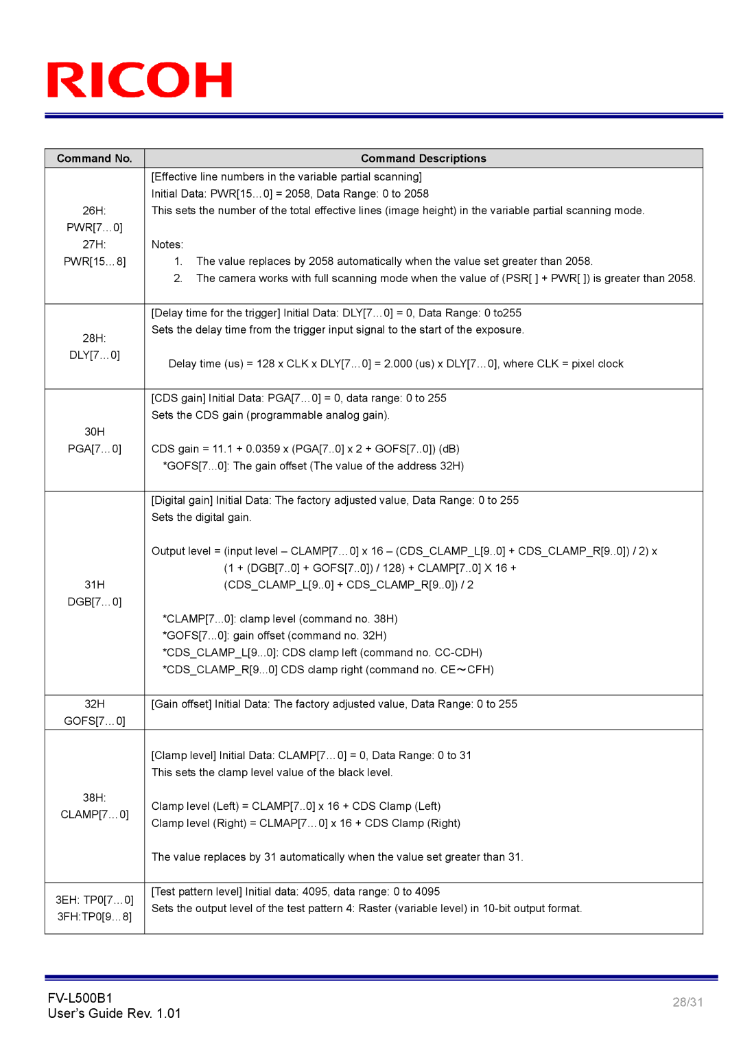
FV-L500B1 specifications
The Ricoh FV-L500B1 is a versatile and advanced multifunctional device designed for businesses needing efficient printing, scanning, and copying solutions. This all-in-one machine combines high-quality performance with user-friendly features, catering to the demands of modern workplaces.One of the standout features of the Ricoh FV-L500B1 is its exceptional printing capabilities. With a print resolution of up to 1200 x 1200 dpi, the device produces sharp and vibrant documents, making it ideal for both text-heavy reports and rich color graphics. Additionally, the FV-L500B1 boasts impressive print speeds, allowing users to handle large volume jobs with ease. Its capacity for duplex printing further enhances productivity by saving time and reducing paper usage.
The scanning functionality of the FV-L500B1 is equally robust. It offers high-speed scanning, capable of handling multiple pages quickly, which is particularly useful for digitizing large documents or archiving paper files. The device supports various scanning formats, ensuring compatibility with a range of digital workflows. Advanced features such as optical character recognition (OCR) allow users to convert printed text into editable digital formats, streamlining document management processes.
Connectivity is another significant aspect of the Ricoh FV-L500B1. The device supports a variety of connectivity options, including USB, Ethernet, and wireless connections. This flexibility allows users to print and scan from multiple devices, including smartphones and tablets, enhancing collaboration in a dynamic work environment. The inclusion of cloud integration further elevates its capabilities, enabling easy access and sharing of documents across platforms.
The FV-L500B1 is also designed with user convenience in mind. Its intuitive touchscreen interface makes navigation simple and efficient, allowing users to quickly access functions and customize settings according to their needs. Additionally, a range of security features ensures that sensitive information remains protected during printing and scanning processes.
In terms of sustainability, Ricoh emphasizes eco-friendly practices through energy-efficient operation and the use of recyclable materials. This commitment not only helps businesses reduce their environmental footprint but also supports cost-effective printing solutions.
In summary, the Ricoh FV-L500B1 is a powerful and multifunctional device that caters to the diverse needs of today’s workplaces. With its high-quality printing, efficient scanning, extensive connectivity options, user-friendly interface, and eco-conscious design, this device stands out as a reliable choice for businesses aiming to enhance their productivity and streamline document management.

