No. 690 Portable Power Drive
Threading with 11-R Die Head
1.For 11/2″ - 2″
end first, squarely into the Power Drive until the spring engages securely (Figure 3). For 1/8″ - 11/4″
NOTE! Installation can be made from only one side of the Power Drive.
Figure 3 – Installing No. 11-R Die Heads
2.If possible, secure the pipe in a portable tristand vise or a bench vise.
![]() WARNING To prevent tipping, long lengths of pipe should also be supported with pipe stand.
WARNING To prevent tipping, long lengths of pipe should also be supported with pipe stand.
3.Be sure the 418 Oiler is properly filled with RIDGID Thread Cutting Oil. Position the oiler in front of the vise.
4.Position No. 691 Support Arm on pipe so end of support arm is in line with end of the pipe (Figures 4 & 5). Make sure jaws squarely contact pipe and tighten handle firmly to prevent slipping of the jaws.
![]() WARNING To avoid serious injury from losing control of the Power Drive, a support arm should be used when threading 3/4″ or larger pipe.
WARNING To avoid serious injury from losing control of the Power Drive, a support arm should be used when threading 3/4″ or larger pipe.
When threading pipe less than 3/4″ in size without a sup- port arm, hold onto the Power Drive firmly with one hand to exert pressure against the handle forces developed dur- ing threading.
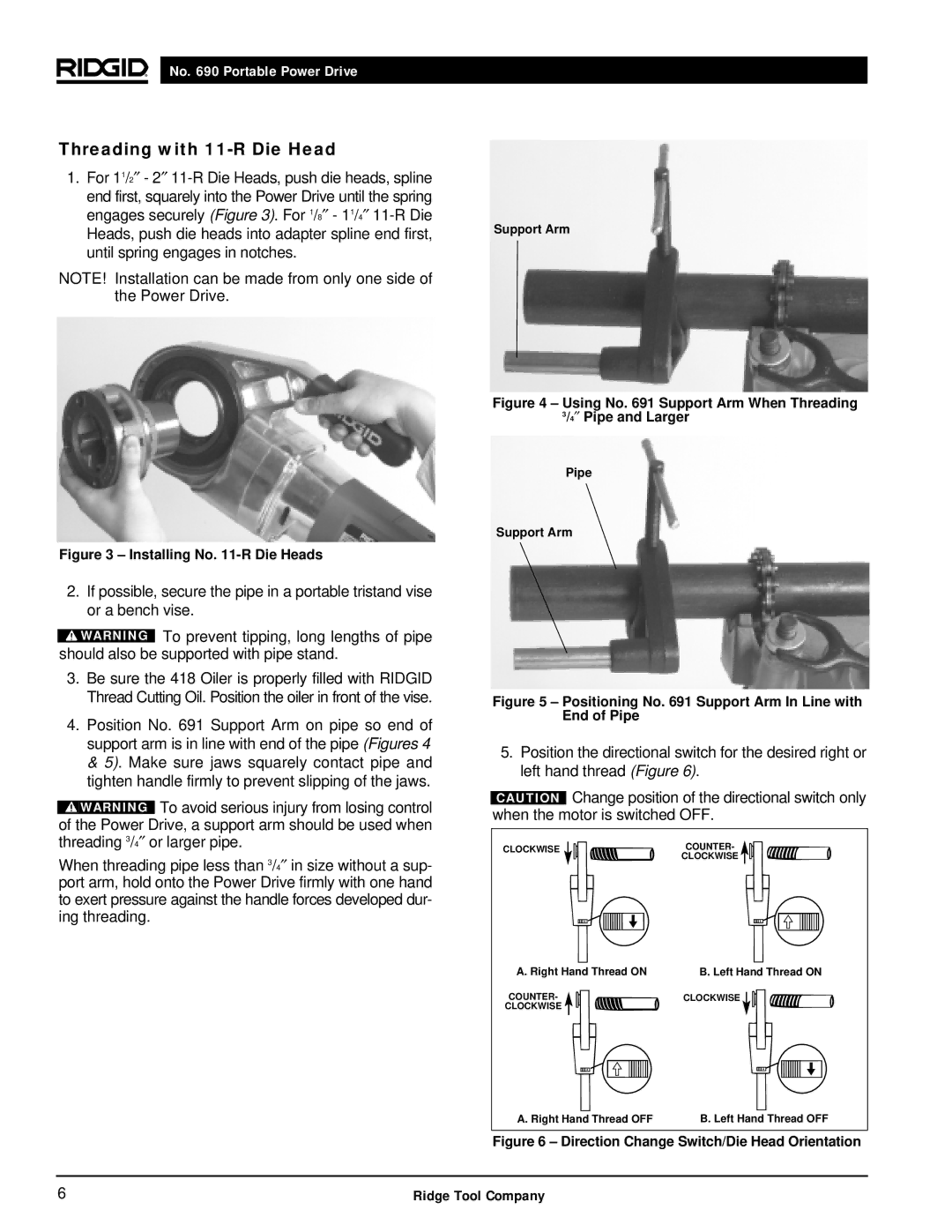
Support Arm
Figure 4 – Using No. 691 Support Arm When Threading 3/4″ Pipe and Larger
Pipe
Support Arm
Figure 5 – Positioning No. 691 Support Arm In Line with End of Pipe
5.Position the directional switch for the desired right or left hand thread (Figure 6).
CAUTION Change position of the directional switch only when the motor is switched OFF.
CLOCKWISE |
|
|
|
|
|
|
|
|
|
| COUNTER- |
|
|
|
|
|
|
|
|
|
|
| CLOCKWISE |
|
|
|
|
|
|
|
|
|
|
|
|
|
|
|
|
|
|
|
|
|
|
|
|
|
|
|
|
|
|
|
|
|
|
|
|
|
|
|
|
|
|
|
|
|
|
|
|
A. Right Hand Thread ON | B. Left Hand Thread ON | ||||||||||||||
COUNTER- | CLOCKWISE |
|
|
|
|
|
| ||||||||
| |||||||||||||||
CLOCKWISE |
|
|
|
|
|
|
|
|
|
|
|
|
|
| |
|
|
|
|
|
|
|
|
|
|
|
|
|
|
|
|
|
|
|
|
|
|
|
|
|
|
|
|
|
|
|
|
|
|
|
|
|
|
|
|
|
|
|
|
|
|
|
|
|
|
|
|
|
|
|
|
|
|
|
|
|
|
|
|
|
|
|
|
|
|
|
|
|
|
|
|
|
|
|
|
A. Right Hand Thread OFF | B. Left Hand Thread OFF |
Figure 6 – Direction Change Switch/Die Head Orientation
6 | Ridge Tool Company |