
MS1065LZA specifications
The RIDGID MS1065LZA is a high-performance miter saw designed for professional contractors and serious DIY enthusiasts alike. Known for its precision and versatility, this tool stands out in its category due to several key features and advanced technologies that enhance its functionality and ease of use.One of the primary characteristics of the MS1065LZA is its robust 15-amp motor, which delivers a formidable 5,200 RPM. This powerful motor ensures smooth, consistent cuts through various materials including hardwood, softwood, and composite materials. Coupled with a 10-inch carbide-tipped blade, the saw is capable of making precise crosscuts and miter cuts, offering users the ability to tackle an array of projects with confidence.
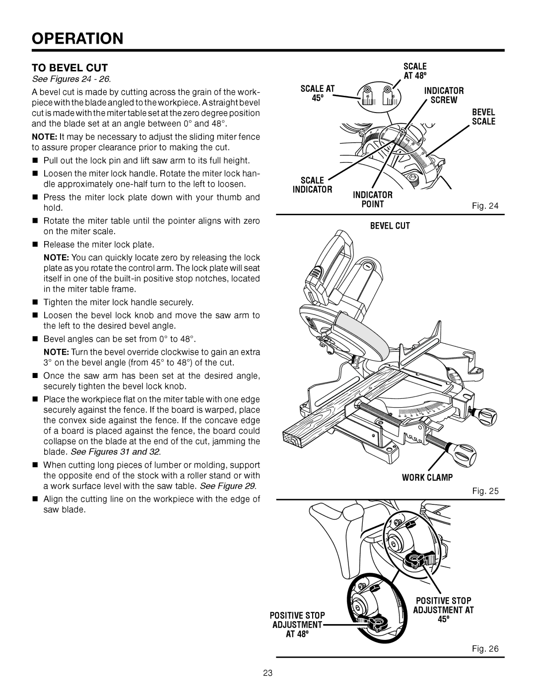
The MS1065LZA includes an adjustable miter range of 0 to 60 degrees to the right and 0 to 52 degrees to the left, allowing for increased flexibility when making angled cuts. The dual bevel feature enables users to easily create bevel cuts in both directions without having to flip the material, which saves time and improves efficiency. The miter saw is also equipped with positive stops at common angles, ensuring quick and accurate settings.
Another notable feature is the innovative laser lighting system, which provides a clear cutting line for improved accuracy. This integrated laser guide helps users align their cuts precisely, reducing the likelihood of errors and waste material. Additionally, the transparent blade guard offers enhanced visibility while keeping the user safe during operation.
The MS1065LZA boasts a large, sturdy base that adds stability and supports larger workpieces, accommodating various project sizes. Its lightweight design enhances portability, making it easier to transport between job sites. The saw also comes with a dust bag that helps minimize mess, keeping the workstation cleaner while cutting.
In terms of user-friendly features, the large ergonomic handle enhances comfort during extended use. The saw is designed with easy-to-read scales and a simple locking mechanism for effortless adjustments. With its combination of power, precision, and practicality, the RIDGID MS1065LZA stands out as a top choice for professionals seeking reliable performance and exceptional results in their woodworking projects.