SECTION 18: DETACHABLE TRAY
18.1 Diagram
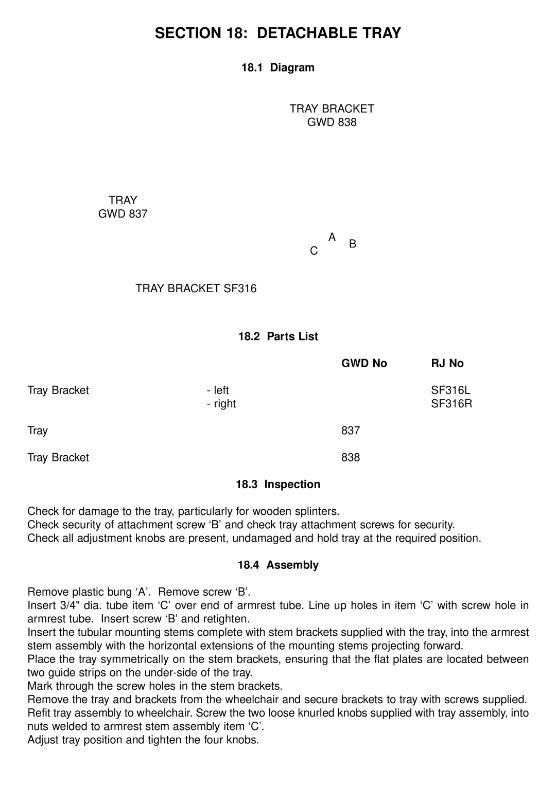
TRAY BRACKET
GWD 838
TRAY
GWD 837
A
C
TRAY BRACKET SF316
B
| 18.2 | Parts List |
|
|
| GWD No | RJ No |
Tray Bracket | - left |
| SF316L |
| - right |
| SF316R |
Tray |
| 837 |
|
Tray Bracket |
| 838 |
|
| 18.3 | Inspection |
|
Check for damage to the tray, particularly for wooden splinters.
Check security of attachment screw ‘B’ and check tray attachment screws for security. Check all adjustment knobs are present, undamaged and hold tray at the required position.
18.4 Assembly
Remove plastic bung ‘A’. Remove screw ‘B’.
Insert 3/4" dia. tube item ‘C’ over end of armrest tube. Line up holes in item ‘C’ with screw hole in armrest tube. Insert screw ‘B’ and retighten.
Insert the tubular mounting stems complete with stem brackets supplied with the tray, into the armrest stem assembly with the horizontal extensions of the mounting stems projecting forward.
Place the tray symmetrically on the stem brackets, ensuring that the flat plates are located between two guide strips on the
Mark through the screw holes in the stem brackets.
Remove the tray and brackets from the wheelchair and secure brackets to tray with screws supplied. Refit tray assembly to wheelchair. Screw the two loose knurled knobs supplied with tray assembly, into nuts welded to armrest stem assembly item ‘C’.
Adjust tray position and tighten the four knobs.