DESIGN FEATURES
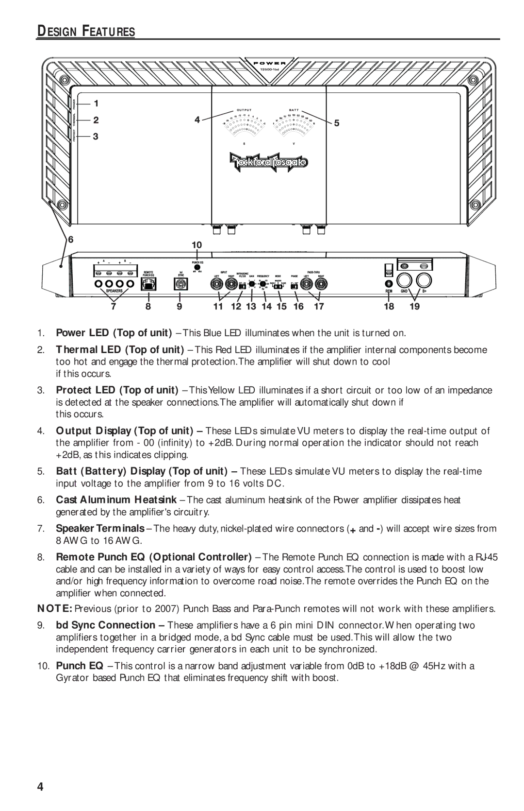
1. | Power LED (Top of unit) – This Blue LED illuminates when the unit is turned on. | |
2. | Therm l LED (Top of unit) – This Red LED illuminates if the amplifier internal components become | |
| too hot and engage the thermal protection.The amplifier will shut down to cool | |
3. | if this occurs. | |
Prot | LED (Top of unit) – This Yellow LED illuminates if a short circuit or too low of an impedance | |
| is detected at the speaker connections.The amplifier will automatically shut down if | |
4. | this occurs. | |
Output Display (Top of unit) – These LEDs simulate VU meters to display the | ||
| the amplifier from - 00 (infinity) to +2dB. During normal operation the indicator should not reach | |
5. | +2dB, as this indicates clipping. | |
Batt (Batt ry) Display (Top of unit) – These LEDs simulate VU meters to display the | ||
6. | input voltage to the amplifier from 9 to 16 volts DC. | |
Cast Aluminum Heatsink – The cast aluminum heatsink of the Power amplifier dissipates heat | ||
7. | generated by the amplifier's circuitry. | |
Speaker Terminals – The heavy duty, | ||
8. | 8 AWG to 16 AWG. | |
Remote Punch EQ (Option l Controller) – The Remote Punch EQ connection is made with a | ||
| cable and can be installed in a variety of ways for easy control access.The control is used to boost low | |
| and/or high frequency information to overcome road noise.The remote overrides the Punch EQ on the | |
| amplifier when connected. | |
NOTE: Previous (prior to 2007) Punch Bass and | ||
9. | bd Sync Connect on – These amplifiers have a 6 pin mini DIN connector.When operating two | |
| amplifiers together in a bridged mode, a bd Sync cable must be used.This will allow the two | |
10. | independent frequency carrier generators in each unit to be synchronized. | |
Punch EQ – This control is a narrow band adjustment variable from 0dB to +18dB @ 45Hz with a | ||
| Gyrator based Punch EQ that eliminates frequency shift with boost. | |
4
