Manuals
/
Rose electronic
/
Computer Equipment
/
Switch
Rose electronic
CAT5
manual
Installation
Models:
CAT5
1
18
32
32
Download
32 pages
59.14 Kb
15
16
17
18
19
20
21
22
Troubleshooting
Install
Warranty
Maintenance
Connectors
Safety
Applying power
Appendix C. Firmware updates
Features
Page 18
Image 18
Page 17
Page 19
Page 18
Image 18
Page 17
Page 19
Contents
Houston, Texas
10707 Stancliff Road
Phone 281
INSTALLATION AND OPERATIONS MANUAL
LIMITED WARRANTY
CE DECLARATION OF CONFORMITY
FEDERAL COMMUNICATIONS COMMISSION AND INDUSTRY CANADA
RADIO-FREQUENCY INTERFERENCE STATEMENTS
FCC/IC STATEMENTS, EU DECLARATION OF CONFORMITY
Figures
TABLE OF CONTENTS
Contents
Tables
INTRODUCTION
Disclaimer
System introduction
Features
Compatibility
Package contents
DVI or VGA
MODELS
Receiver Transmitter Local KVM access Transmitter No local KVM access
Connectors
PC model
Rack model
CrystalView Pro CAT5 cables
CrystalView Pro CAT5 to Rose switch cable
CABLES
Transmitter unit to CPU cable
ON-SCREEN DISPLAY OSD
Device Control - OSD
Select graphic source menu
The brightness / contrast menu enables you to adjust
Figure 5. Color / Color temp menu
Figure 6. Image menu
Figure 7. Tools menu Manually adjust the OSD
No auto-detection of pixels and phase
INSTALLATION
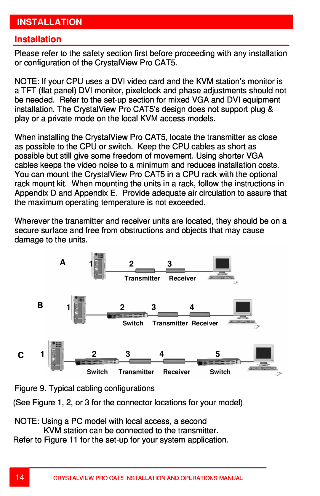
Installation
Maximum distance
Transmitter to Receiver cabling
Cable type
CAT-5
SET-UP instructions Mixed DVI and VGA
Pixel clock set correctly
Applying power
Operating instructions
Operating instructions - Local KVM access
OPERATING INSTRUCTIONS
Frame Rates
PC boots with no error messages but keyboard does not work
TROUBLESHOOTING
Troubleshooting
Wrong or missing characters from those typed
Smeared characters
Maintenance and Repair
SERVICE
Service Information
Technical Support
SAFETY
Safety
Safety and EMC Regulatory Statements
Safety information
Grounding
Servicing
Appendix A. General specifications
APPENDICES
Part Number
Appendix C. Firmware updates
Appendix B. Parts and cables
Description
Appendix D. Rack mount instructions
Appendix E. Rack mount illustration
10707 Stancliff Road
Phone 281
Houston, Texas
Top
Page
Image
Contents